Hi There,
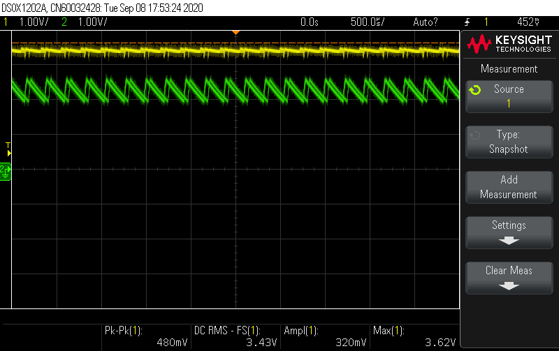
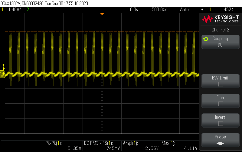
Please find below the schematic. I apply 3.5V at the input, but the converter doesn't seem to be boosting the output to 5V. Output is around 2.62V. Also, I have 3 22uF capacitors at the output. Please help me debug this.
Hi There,
Please find below the schematic. I apply 3.5V at the input, but the converter doesn't seem to be boosting the output to 5V. Output is around 2.62V. Also, I have 3 22uF capacitors at the output. Please help me debug this.