This thread has been locked.

If you have a related question, please click the "Ask a related question" button in the top right corner. The newly created question will be automatically linked to this question.

LM5069: Issue in DC Input protection & Hot-Swap

Part Number: LM5069
Other Parts Discussed in Thread: TPS2663

Hi,

We are using TI's Hot swap controller LM5069 along with other 3rd party Sidactor & TVS protection devices in our DC powered Ethernet Switch product and are facing following challenges,

During IEC 61000-4-2 ESD tests (2KV/4KV contact discharge), the external AC-DC power supply powering our equipment shuts down (probably due to over voltage protection).
During IEC 61000-4-4 EFT tests, external power supply shuts down when power is applied to our equipment through a captive coupling device. The EUT (our Equipment) doesn't even power up if power is applied through a CDN.
During IEC 61000-4-5 Surge tests, The EUT (our Equipment) doesn't even power up if power is applied through a CDN.

In normal use case, the EUT is powering & functioning properly without any issues. Let me know if TI can review our input power protection & DC-DC section of the schematic.

Regards,
Jaison

  • Hi Jaison,

    Sure. Please share the schematics and system block diagram for review.

    Also, please share the system specifications (voltage, current)

    Best Regards, Rakesh

  • Switch-DC-Input-Section-1.6.pdf

    Hi Rakesh,

    sorry for the delay from my end in following up on this.

    We figured out the at the SIDACtors used at DC input side is not meant for DC and replaced them with TVS diodes. We are able to qualify the ESD tests with this change.

    However, the EFT & Surge is still an issue as the EUT is not even powering up when the DC power is supplied through the CDN. Please refer to the attached schematic section of DC power input & hot-swap section. With CDN we find that the DC is reaching till the input side of the Hot-swap FET, but the Gate of FET is staying around 10V and hence the FET is not getting ON. We do not see any uv/ov conditions here. The Test is not even started and so we don't suspect any issues with respect to the spikes introduced by any test case.

    We also did one test by bypassing the hot-swap FET and system got powered up in this case.

    Let me know what can be the cases where the host swap controller keeps the FET off when the DC power input is connected through a CDN. During normal case where the power input is directly connected to EUT, it comes up without any issues.

    The power rating is 42 to 57V DC, 6A. The test were carried out with a 54V DC input.

    Thanks,

    Jaison

  • Hi Jaison,

    EFT and Surge events generate fast transients which creates differential voltage across the current sense resistor and shuts down the GATE of LM5069. Can you add differential filter as per Figure -11 in https://www.ti.com/lit/an/slva703/slva703.pdf and check

    Best Regards, Rakesh

  • Hi Rakesh,

    Thanks for the feedback & recommendation.

    In our case, The hot-swap is not even turning ON the FET when power is supplied through the CDN. This happens even without applying any EFT or surge.

    Is this possible if we don't have this recommended differential filter circuit on the hot swap?

    Thanks,

    Jaison

  • Hi Jaison,

    Ok. Got it.. Can you please check whether the CDN introduces any kind of common-mode noise into the line ? That could be one possibility, I can think of.

    Can you place your EMI filter at the input of the hot-swap instead of at the output and verify.

    Best Regards, Rakesh

  • Hi,

    We Tried RC filter on hot-swap sense pin with 0.3E and 1uF. When powered ON, MOSFET output was coming around 9V only. 3.3V regulator didn’t turn ON. Then tried removing PoE power cable(this is PSE EQUIPMENT), then LED started flickering where 3.3V was around 2.5V and hot-swap MOSFET output was around 11V. In both cases MOSFET gate voltage was almost equal to drain voltage

    Next we tried wiring EMI filter externally without PoE daughter card power connected, this time 3.3V power was reaching upto 3.3V and then decaying down. After 2-3 power cycle, 3.3V regulator stopsped working. After 3.3V regulator stopped working, hot-swap MOSFET output is properly coming to 54V. But when tried with PoE cable connected hot-swap MOSFET output is coming around 9V only. In SL# 02 board looks like 3.3V regulator is gone bad.

    In SL# 03 board we bypassed MOSFET and continued EFT test for 1KV and 2KV. Both test cases passed.

    In surge test, 500V surge applied in both differential and common mode. Both test cases passed.

    When 1KV surge applied in differential mode, after 3rd pulse, PoE devices went down. During this time system was still up and running and ping traffic was also through between laptops. Here looks like something on PoE daughter card is damaged.

    Let me know what causes the hot swap to keep the mosfet  off during eft/surge tests.

    3.3V dc dc is a non isolated design based on TI solution as i shared in the schematic. Can the non isolated design cause issues in these tests?

    Thanks,

    Jaison

  • Hi Jaison,

    The LM5069 controller turns OFF the FET for overcurrent during surge/EFT events. Can you probe Vin, GATE, input current and timer voltages during the test and share us to review.

    Best Regards, Rakesh

  • Hi Rakesh,

    Does it mean that LM5069 is not meant for application where EFT/Surge certifications are required?

    Does TI has any other hot swap controller that supports EFT/Surge?

    I will share the requested plots when we do the next trial as these test are done at a 3rd party lab.

    Do you have any suggestions on how to do this or similar tests in a normal lab set-up without EFT or Surge test equipment? Any app-note or guidelines will be helpful in trouble shooting this issue as we are always dependent on the 3rd party compliance lab for this.

    Regards,

    Jaison

  • Hi Jaison,

    For fast transients such as surge/EFT, the devices hits fast-trip and recovers back. so, a large Cout at the output would help to serve the load while the LM5069 covers. Faster the device recovers, lower will be the Cout requirement.

    We have better solution TPS2663 where the device recovers the GATE with boost charge so Cout requirement can be minimized. Please look at the TPS2663 and let me know.

    Best Regards, Rakesh

  • Hi Rakesh,

    This design need to support a current of around 10A and TPS2663 supports upto 6A only.

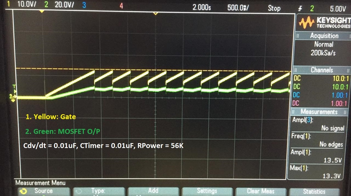
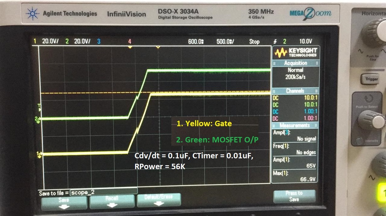
    We did one more trial with LM5069 and got the system powered up through the CDN. But, the system got power cycled when EFT test was applied.

    This was achieved by adding the dv/dt start-up ckt. PFA some captures taken when it was just powered. We were not able to capture anything when the EFT was applied due to some limitation of the scope in measuring 1kV spikes.

    Regards,

    Jaison

  • Hi Jaison,

    Good to hear that. In the above two test waveforms, can you include Timer voltage and input current waveforms to understand why it is falling to startup. Is it due to timing out due to load at the startup ?

    Two of the TPS2663 devices can be used in parallel to support 10A. please refer https://e2e.ti.com/support/power-management/f/196/p/955040/3530866#3530866 

    Best Regards, Rakesh