This thread has been locked.

If you have a related question, please click the "Ask a related question" button in the top right corner. The newly created question will be automatically linked to this question.

BQ24133: When using a DC-DC with BQ, there is a dead time when switching from psu to battery operation

Part Number: BQ24133
Other Parts Discussed in Thread: CSD17313Q2,

For my project, I want to use a single cell li-pol 3.7V battery to power a device that needs 12V, instead of having a 3 cell battery. I tried to do this:

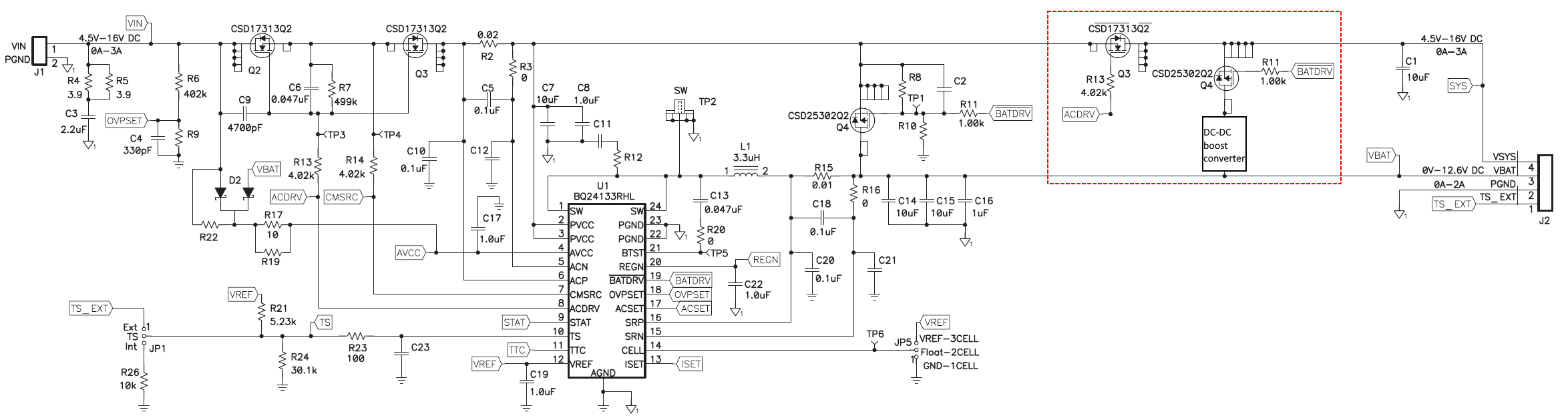
From my earlier post, the issue was I believe in the transistors. At the time I didn't have the CSD17313Q2, so I used a generic SOT23 nmos as the additional transistor. I think the timings affected the IC since that transistor might've been still open while BATDRV pmos is open too.

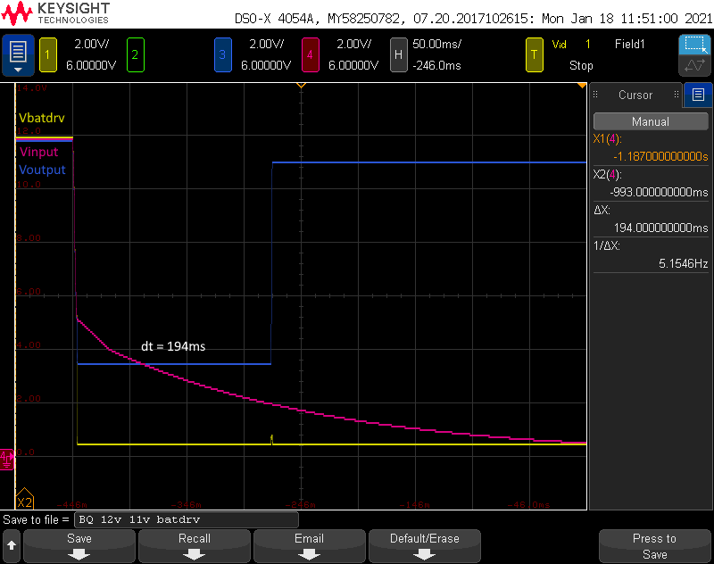
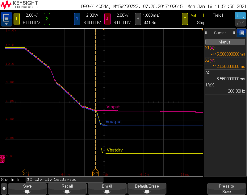
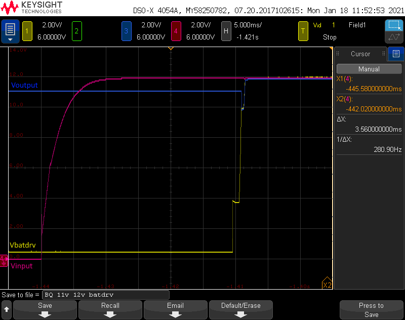
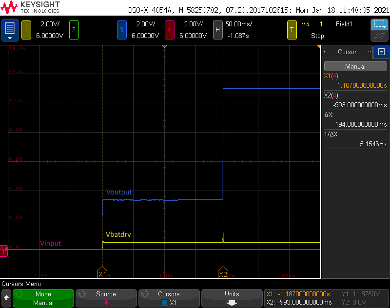
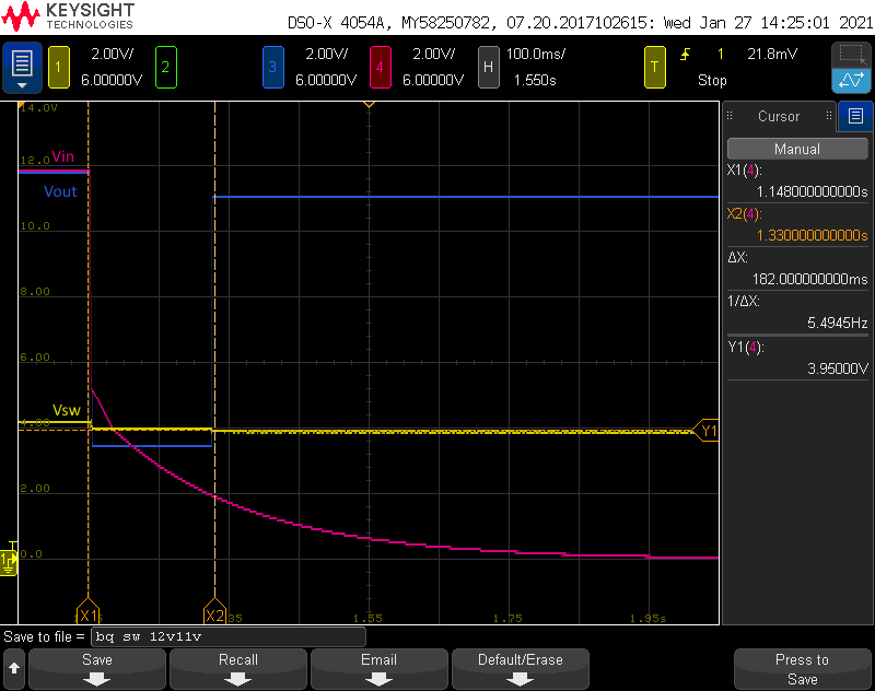
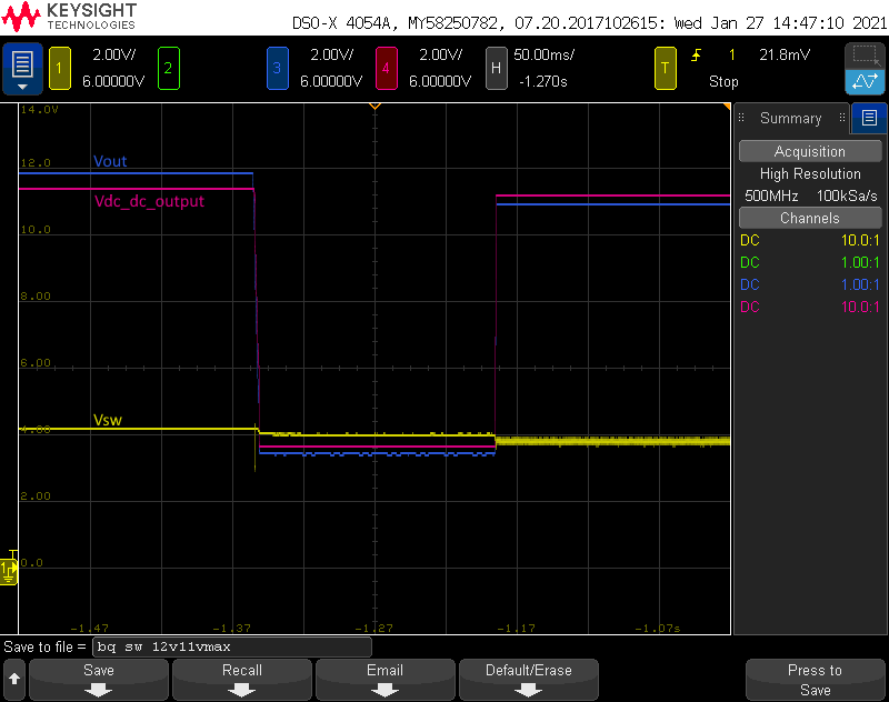
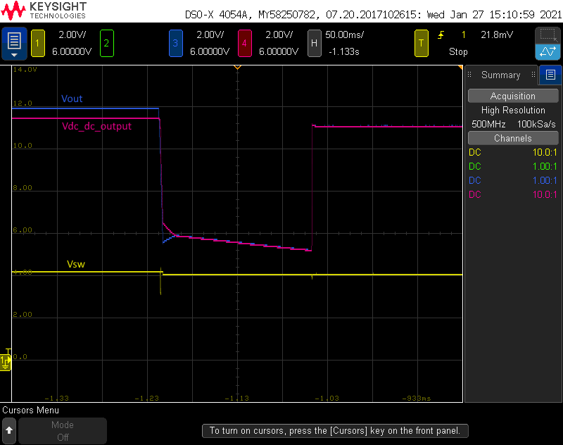
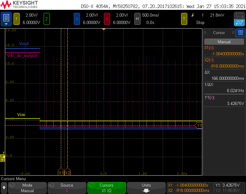
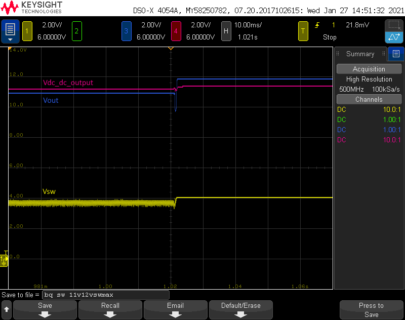
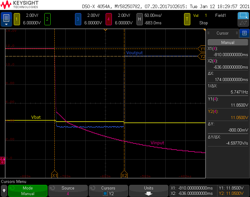
As of right now, the circuit works as expected after switching to CSD17313Q2 and remaking the pcb, until I try to switch to the battery operation from PSU. When I switch, there is a 150-200ms delay until the DC-DC starts boosting. The DC-DC IC is MAX17112. I am using a 150mA constant load. Here are some waveforms from the o-scope:

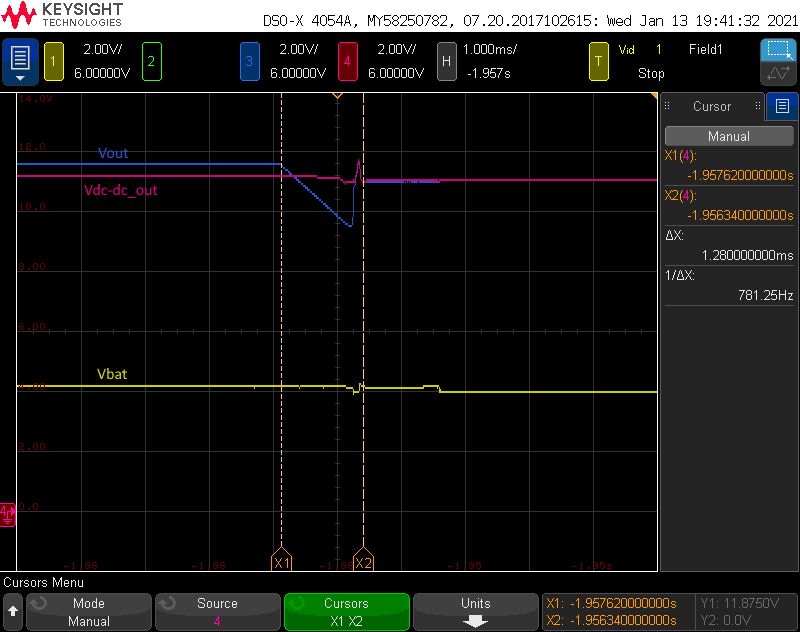
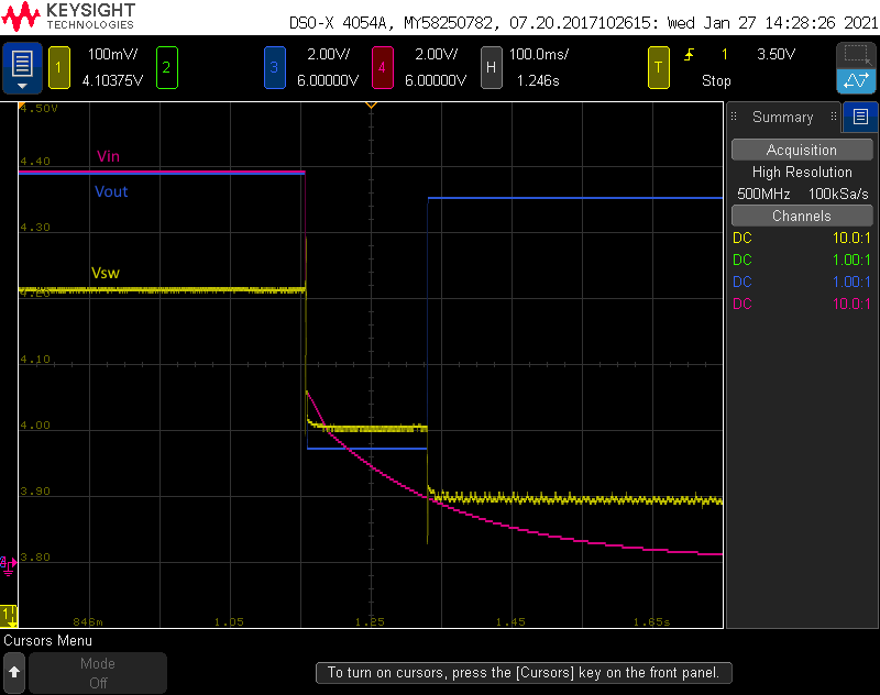
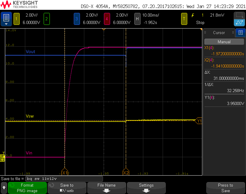
Here is just the DC-DC by itself when operating without load and switching to with load:


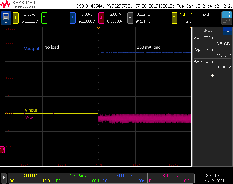
As you can see, there is no delay in applying a load to the DC-DC. I'm not sure why these two ICs behave like this.

  • I removed my additions from the circuit (by cutting the traces and adding jumper wires) and here is the transition waveform:

    I don't think the issue is in the ICs.

    I decided to test by replacing the transistor with a Schottky diode. Here is the transition waveform:

    Seems like the issue is with the transistor. I'm guessing the problem is when the transition happens. I think the transistor is still open and there is a short-circuit happening with the battery and dc-dc output and hence the DC-DC fails to output the voltage.

  • Aslan,

    More concisely, the BQ24133 is behaving as expected, is my understanding correct?

    Best Regards,

    Ricardo

  • Dear Ricardo,

    Yes, the BQ24133 is working as expected, I believe.

  • Aslan,

    Please create a new thread with the CSD17313Q2 team to work on resolving your MOSFET issue.

    Best Regards,

    Ricardo

  • Ricardo,

    I am still unaware what's the real issue here. I think the issue is in the transistor, but not sure what to do. I think the transistor is still open when supplying from the battery and there is a current loop, causing a short circuit, which is why the DC DC fails to output 11V. Again, this is my thinking and I would like to get insight on this issue. While the BQ24133 is working as expected, my issue is still tied to it, not the transistor. Because I would get a similar issue with any transistor.

    Aslan

  • Aslan,

    What does /BATDRV look like? 

    Best Regards,

    Ricardo

  • Ricardo,

    Here are the waveforms:

    - with 150mA load, switching from powering from PSU to battery with DC-DC:

    - above waveform but zoomed in:

    - with 150mA load, switching from battery with DC-DC to PSU:

    - with 150mA load, switching from no power (Vinput and battery are disconnected) to connecting the battery:

    Even when there was no power from Vinput initially present, there is still a dead time when switching to powering from battery with DC-DC.

  • Aslan,

    Are you also seeing a dead time if you drive the FET externally with a different signal?

    Best Regards,

    Ricardo

  • Ricardo,

    I haven't tried that and I don't have the equipment to test that. Regarding the last waveform, I realized it's because of the soft-start of the DC-DC. I feel like the issue is not with the transistor not opening but on the contrary. I think the transistor is still open when transitioning to battery power. I am certain that current is going the other way (blue line) between dead time and turn off of PSU, because when I disconnect Q5 and put D4, everything works as it should. I'm just not sure where the short circuit is happening. From my understanding, the only nodes where current can potentially flow into are: PVCC, ACN, ACP, Vbat

    I thought that the current later goes through Q4 back to the battery, so I put a diode D3 instead of Q4, but it still behaived with dead time.

    Looking into the block diagram of the BQ:

    I see that there is a transistor connected to from PVCC to SW to PGND. Perhaps current is going there?

  • Aslan,

    It seems there is a boost back issue caused by the inductor of the boost converter. I suggest adding a schotkky diode between PVCC and the output of Q4 to prevent this issue.

    Best Regards,

    Ricardo

  • Ricardo,

    This solution is nearly identical to the one where I replace Q5 with a diode. I wanted to eliminate diodes in high current paths, that's why I didn't settle on the solution with a diode. Power losses with a diode would be too high. Is there a way to have minimal power losses?

  • Aslan,

    When the adapter is not present (running on battery power) you are suffering conduction losses on the Q5 body diode. There's not really a way to avoid the power losses as you are relying on that potential differential for isolation to prevent boost back.

    Best Regards,

    Ricardo

  • Ricardo,

    I'm not sure when the forward diode would be conducting and Q5 itself won't. Voltage on the source of the MOSFET is higher than drain, only when powered from adapter, hence the gate should be source+6V - open. At Vgs around 6V Rds_on is 25mΩ, so the conduction losses should be minimal and magnitudes less than from just a Schottky diode.

    When running on battery power, voltage on the drain is around 12V, while on the source it's Vbat (3.7V). The gate voltage on Q5 should be at CMSRC, which is low, leaving the transistor in off state. The body diode won't conduct. 

  • Aslan,

    Ultimately I cannot offer you a solution to avoid the boost back issue without a diode.

        Best Regards,

              Ricardo

  • Ricardo,

    Could you explain in detail about the boost back issue?

  • Aslan,

    Could you capture the SW node during this phenomenon?

    Best Regards,

    Ricardo

  • Ricardo,

    There are the waveforms:

    Zoomed in when transitioning:

    Same as above, but scaling for Vsw is 100mV, instead of 2V

    Here is Vsw from the DC-DC circuit:

    I wasn't fully sure what Vsw you wanted, so I'm including both.

    Here is without load:

    Here is when the load is too much for the DC-DC circuit to handle:

    It turns off for about 160-170ms before turning back on, only to realize that the load is too much.

    Here is the transition from powering from the battery+DC-DC to adapter zoomed in:

    Vsw of the DC-DC circuit when transitioning to the adapter:

  • Ricardo,

    I'm fairly certain, looking at the waveform where there's no load, that the issue is in the DC-DC controller not being able to supply enough instantaneous current during the transition. I'm sure that if I use a more powerful controller, it would be able to handle it and not turn off for a period of time. However, there is an underlying issue that needs to be solved. That instantaneous current will most likely damage something in the circuit. I don't see the effects of the damage right now, simply because the DC-DC controller is limiting the voltage. Is there any way it's possible to speed up the closing of the nmos Q5 transistor or delay the opening of the pmos Q6 transistor? 

    Aslan

  • Aslan,

    I agree. You are better off trying to slow down the PMOS rather than speeding up the NMOS. The simplest fix would be to add shunt capacitance to the PMOS gate. 

    Best Regards,

    Ricardo