
- Ask a related questionWhat is a related question?A related question is a question created from another question. When the related question is created, it will be automatically linked to the original question.
I would like to generate a split supply from USB VBUS (4-5.25 V). Anything above ±4 V would be ok, but no more than ±6 V (and they don't need to be exactly symmetrical). It needs to supply no more than 20 mA from both outputs. It needs to be possible to shut it down completely, so a chip with synchronous switch inside that opens during shutdown would be good (or external diode with FET in series to shut it down).
I used the design tools to find the TPS61220, and am wondering if I can add a charge pump to it, for the negative supply, like this article:
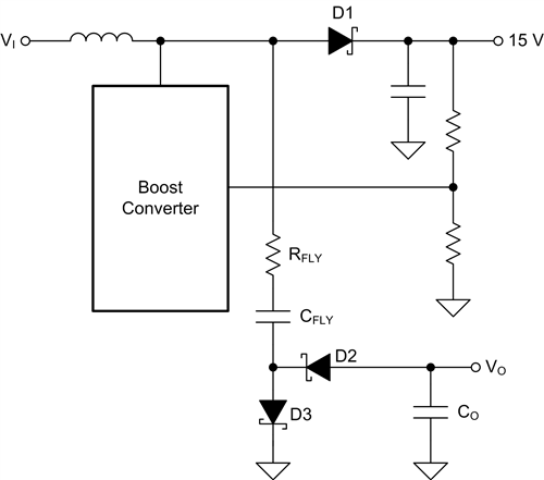
However says "To avoid disrupting boost converter operation, it’s a good idea not to load the switch node too much. A good rule of thumb is to make sure that the charge pump’s output power is less than 10% to 20% of the boost converter’s output power." and I want them to be the same. Is that not possible?Pump it up with charge pumps – part 3
The product line I work in develops multirail power supplies for LCDs and AMOLED displays. It is common for such supplies to feature one or more inductive converters, plus a couple of charge pumps to generate additional low-power output voltages. Charge...
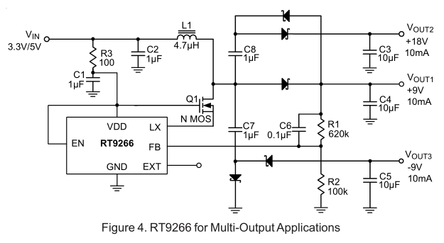
Something like this, which shows similar currents at both outputs:
I tried simulating it in TINA:

but it takes a very long time to simulate, making me suspicious, and the transient simulation doesn't show the inductor current switching at all.
Any advice?


