This thread has been locked.
If you have a related question, please click the "Ask a related question" button in the top right corner. The newly created question will be automatically linked to this question.
Hi,
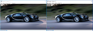
I want to create a custom LUT, for testing purposes I tried to create a Mesh table that just shifts the image to right by 100 pixels.
I tried to create LUT with the tool provided vision SDK when I have checked the output it was all 0. I guess this is incorrect because if the value of LUT will be 0 the there will be no back mapping.
I think I'm missing something. Could you please help me to understand how can I create a custom LUT?
For this purpose, I have referred following thread -
Regards,
Amir Ansari
Hi Amir,
Your "(h_d - h_p, v_d - v_p)" should be "(800, 0)".
So your "mesh.txt" looks like:
800 0 800 0 800 0 ......
The number of lines depends on your image size (W x H) and LUT down sampling factor (m).
Typically, it is "ceil(W / 2^m + 1) * ceil(H / 2^m + 1)" lines.
Then, you may use the "convert.sh" tool.
Best,
Gang
Hi Gang,
As you suggested, I have created mesh table and then LUT for 1280x720 input resolution. But when I am giving 800 0 offsets, I am getting input image shifted to left by 100 pixels. If I give -800 0 offsets then I am getting correct output i.e. input image shifted to right by 100 pixels. Following are the results for -800 0 offsets. Can you please tell me why this is happening?
Hi Pooja,
The LUT is for back mapping, i.e., output coordinates to input coordinates.
For example, output pixel at (x=0,y=0) is back mapped to input image at (800/8, 0).
Best,
Gang
Hi Gang,
Thanks for quick response. As stated in original requirement I want to shift the input image to right by 100 pixels in output. Hence, as per the formula [h_d-h_p, v_d-v_p] will be [-800 0]. But in your above reply you have stated to keep value [800 0],hence wanted to confirm.
Also we have 2 questions
1. one observation was that the out of bound values are not becoming 0. Is there any way to do so?
2. How down sized table creating the output exactly as the size of input if back mapping is happening for each index of output pixel?
Regard,
Pooja
Ok, this might be misunderstanding:
>> for testing purposes I tried to create a Mesh table that just shifts the image to right by 100 pixels
It sounds like to me you were trying to map output pixel at (x,y) to input pixel at (x+100, y), i.e., grabbing the right part of the input image.
>> 1. one observation was that the out of bound values are not becoming 0. Is there any way to do so?
No, that is a H/W limitation. LDC will repeat the value of the board pixels.
A possible workaround is to pad your input images with black borders (or any other color you like).
>> 2. How down sized table creating the output exactly as the size of input if back mapping is happening for each index of output pixel?
I am not sure if I understand the question properly.
LUT is down-sampled to save memory and DDR traffic because LUT is very large without down-sampling.
H/W will interpolate (bi-linear) the LUT internally.
Best,
Gang
The number of lines depends on your image size (W x H) and LUT down sampling factor (m).
Typically, it is "ceil(W / 2^m + 1) * ceil(H / 2^m + 1)" lines.
Hi Gang,
Image size here it's input image size or output? Does the size of mesh.txt depend on output image size in general?
Regards,
Igor Lugansky
Yes, it is the output image size.
We only need information for each output pixel.
Hi Gang,
I am trying to generate 1280x800 resolution output image from 1920x1080 resolution input image using LDC LUT.
As mentioned in IssM2mSimcopLink_CreateParams, I have set below parameters for different output resolution image.
pUcObj->IssM2mSimcopPrm.channelParams[0].useOutputFrameSize = TRUE;
pUcObj->IssM2mSimcopPrm.channelParams[0].outputFrameWidth = 1280;
pUcObj->IssM2mSimcopPrm.channelParams[0].outputFrameHeight = 800;
But when I try to run SIMCOP with this changes application gets hang.
Is there any other configuration parameter need to set for getting different output resolution image?
Regards,
Pooja Jadhav
Hi Pooja,
I am not familiar with S/W details.
It is possible that there are some places in s/w you need to modify in source code so that the sample code can work with different output image size.
I will ask our s/w expert to respond
On LDC tuning side, are you confident about your settings?
Hi Gang,
Yes I have done correct settings as mentioned in above post. Please discuss internally and let me why it is not working.
Regards,
Pooja Jadhav
Hi Pooja,
Thanks for the confirmation!
I have notified our s/w expert.
There should be some other code changes required to a different output resolution.
Pooja,
I think there is a flag in the channel parameter (useOutputFrameSize) to allow usage of output size. By default, output size is always equal to input size, but if you require different output size, please set this flag to true, then you could set the output parameter size differently.
Please refer to vision_sdk\links_fw\src\rtos\links_ipu\iss_m2msimcop\issM2mSimcopLink_drv.c for more information, especially API IssM2mSimcopLink_drvCreate.
Regards,
Brijesh
Hi,
I want to create downsampled mesh table for input resolution 920x1080. Output resolution will be same as input. Offset values will be calculated from equation available with me . How can I create downsampled mesh table for given resolution?
Regards,
Pooja Jadhav
Hi Pooja,
If you can calculate the offsets properly, then you may do that for pixel locations the down-sampling step size.
For example, if your I/O images are both 920x1080 and your down-sampling factor is m=4 (16x16), then
1. You need to calculate your offsets for output pixels locations on the grid of X=[0,16,32,48, ..., 928], and Y=[0,16,32,48, ..., 1088].
2. Put all the offsets in a LUT text file in 2 columns.
3. Try the LUT out in TDA2P ISP DCC tuning tool with your input image and get LDC output block size and padding parameters.
4. Use a Vision SDK script to convert the LUT text file to SDK header or binary format.
5. Try on EVM
Please refer to this FAQ for more details if necessary
Hi Gang,
I/O images are both 920x1080. If I consider no down sampling m=0, then number of lines in mesh.txt will be 921x1081. How this +1 in width and height is mapped? If there is 1 to 1 mapping shouldn't size of mesh.txt be 920*1080?
Regards,
Pooja
Hi Pooja,
First, "m=0" (no down-sampling) is not considered as a valid use case unless for debugging or testing purpose, because it runs much slower than expected 1 or 2 cycles/pixel speed.
Second, technically the "+1" is only needed for "m>0", but H/W design has the same limitation for "m=0" for simplicity.
You may extend either the LUT naturally for the "+1" or fill in 0s for "m=0" case, but don't use "m=0" in your real system if speed matters.
Best,
Gang
Hi Gang,
First, I am using no down-sampling for testing purpose only.
Second, Can you please explain how this "+1" plays role for m>0.
Regards,
Pooja
Hi Pooja,
Sure; "+1" is needed for interpolating the missing (down-sampled) offsets values.
If you have an image with 64 pixels wide and set m=4, you would need LUT entry at x=0, 16, 32, 48, and 64 so that the full LUT can be interpolated.
Hi Gang,
Thanks for the reply . It seems there is a bit of confusion. So let me explain the issue I have while creating mesh.txt
If the image is of 64 pixels and the values of x are in index form starting from 0, the last valid pixel value should be 63 . Index value 64 will be a out of bound value. So how can the value at position 64 be calculated and entered while creating mesh.txt for m=4?
Hi Aniruddha,
>> If the image is of 64 pixels and the values of x are in index form starting from 0
I suppose you are talking about input image here, i.e., input image is 64 pixels wide.
>> Index value 64 will be a out of bound value.
Here, "out of bound" is only meaningful for input image.
For output image and the LUT we create for output image, size can go beyond 64.
Assume the desired output image is also 64 pixels wide (same as input image).
As a simple example, the output image is left half of the input.
Then, output image locations [0, 1, 2, 3, 4, ..., 64] are mapped to input image locations [0, 0.5, 1, 1.5, 2, ..., 32].
We have the 64th location at 64 for output image which is mapped to 32 in input image (no out of bound in this case).
Hi Brijesh,
Is there any restriction of input size that may cause such an issue?
Regards,
Pooja
Hi Pooja,
Do you also change lookup table when you change input size or do you keep the lut constant? Do you see any error reported in the LDC? can you check?
Regards,
Brijesh
Hi Brijesh,
I am assuming you are asking about my second question. For different input resolution, I am changig LUT as per input resolution size. I am not getting any error but usecase gets hang in UV data filling function in nullsrc_tsk.c file.
Regards,
Pooja
Hi Gang,
1. As you suggested I tried our LUT in DCC tool for I/O resolution 1920x1080. When I set tunning method to semi automatic, I am getting following error.
Also in sim_error_log file of DCC I am getting following errors
But I am able to see correct output in tunning output window of DCC tool.
Why this errors are coming and what it means?
2. When I run this LUT on board, getting some distortion in output image which was not observed in DCC tool output. Is there any reason for this distortion?
Regards,
Pooja
Hi Pooja,
1. It means none of the listed block width/height combinations would work without an error on H/W.
I am not sure if it is because of your discontinuous mapping (the vertical boundary between the 2 appearance of the same white car) or the zoom-in factor is too large on the right size of that vertical boundary (LDC running out of internal memory while reading its input image block).
For example, for a 8x8 output image block, the needed input image block is 128x128 with a 16:1 zoom-in factor.
Could you please share your tuning tool project so that I can check your LUT and I/O images?
You may send it via email if you cannot upload on E2E.
2. Tuning tool does simulate the H/W error of running out of internal memory (it just reports an error message and give a good output image).
The distortion (too small to see clearly in your image) on H/W should be coming from LDC running out of internal memory.
Best,
Gang
Hi Gang,
The DCC tool folder and explanation PPT were shared through separate mail.
Please take a look and give comments.
Thanks.
Regards,
James
Hi Pooja,
The mapping you defined in your mesh LUT is not continuous.
Most of the 1080P output image is unchanged from input image (copy from input to output directly).
Only a rectangular area from (X=439, Y=139) on top-left is changed from input image.
On the top/left/bottom sides of that output rectangle, the spatial mapping is discontinuous, i.e., 2 neighboring output pixels are very far apart in input image.
This kind of discontinuity will cause LDC to run out of its internal memory, because the discontinuous boundary goes inside some LDC output blocks.
In general, we shall not use discontinuous mapping with LDC.
1. Is this discontinuous mapping an experiment or your actual desired mapping?
Because the output image looks very weird with this discontinuous mapping (the white car is repeated), I suspect it might be just an experiment and you don't need to worry about the artifacts from running out of LDC internal memory (i.e., you may move on to work on your actual desired mapping that is continuous).
2. If you want to fix the artifacts for this discontinuous mapping, then you may try the following:
- re-define your output rectangle area to align with your output block size.
E.g., if your output block size is 32x20, then move your rectangle to be aligned with the block size, e.g., from (X=439, Y=139) to (X=440, Y=140).
In this way, LDC output blocks are aligned with changed area and won't require huge input block size because of the discontinuity.
That is, the changed rectangle must be covered exactly by output blocks (no boundary crossing).
- generate a new mesh LUT
- use tuning tool with the new mesh LUT to test
Please note that if you want to change your output block size again, you may have to repeat the above 2 steps so that the changed rectangle is still covered exactly by the output blocks.
Best,
Gang
Hello Pooja,
There are several flags (overrideInFrmSize, useOutputFrameSize) in the simcop channel parameters, to override input as well as output frame size. If flags are not set, then link uses frame size from the input/output frame. Please look into the file vision_sdk\links_fw\include\link_api\issM2mSimcopLink.h for further information on flags.. Simcop link is straight forward, could you please put breakpoint on the process API and confirm that your changes are taking effect?
Regards,
Brijesh