This thread has been locked.

If you have a related question, please click the "Ask a related question" button in the top right corner. The newly created question will be automatically linked to this question.

PROCESSOR-SDK-OMAPL138: Communicating Two OMAPL138 kits using MCBSP as master and slave

Part Number: PROCESSOR-SDK-OMAPL138
Other Parts Discussed in Thread: OMAPL138

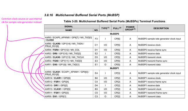
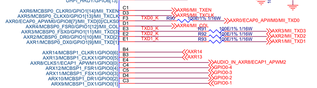
I have a query related to hardware settings of OMAPL138. I am using 2 OMAPL138. How can I physically connect two OMAPL138 using MCBSPs. I want an arrangement such as McBSP of one OMAP should be connected to a McBSP on the other one. In both OMAPs the Tx is master and the Rx is slave.  I want to communicate using MCBSP0 of OMAPL138.

Please guide me.

Regards, 

  • Hello Waseem,

    Are you using Linux or RTOS to control the McBSPs?

    Regards,

    Nick

  • I am using Windows with RTOS program for configuration of mcbsp. I am concerned about hardware connections of two omapl138 kits. Please guide me how i can connect two omapl138 over mcbsps?

  • Please reply to this query as it is really urgent.

  • Hello,

    Please note that TI has stopped supporting TI-RTOS based and bare-metal SW development. Please refer to the announcement.

    I'll loop in our HW expert for further comments.

    Regards,

    Jianzhong

  • yes please... I need guidance regarding hardware changes that are required to access MCBSP0 and MCBSP1 of LCDKOMAPL138.

    Kind Regards.

  • Hi,

    The LCPD was not designed to use either McBSP. The pins are pinmuxed with other functions like Ethernet and GPIO. However, if you modify the board with wires, you could achieve the below McBSP0 to McBSP1 loopback connections
    However, recommend finding a different board for McBSP0/1 loopback if possible.


    Refer to the schematics https://www.ti.com/lit/df/sprcaf3/sprcaf3.zip
    And the datasheet https://www.ti.com/lit/ds/sprs586j/sprs586j.pdf


    The whole McBSP0 set of signals are pinmuxed with MII and are connected to LAN U23 which is a QFN package so you can solder wires to the pins...
    CLKS0 on AXR0/ECAP0_APWM0/MII_TXD0
    MCBSP0_FSR0 on AXR4/MII_COL
    MCBSP0_CLKR0 on AXR6/MII_TXEN
    MCBSP0_DR0 on AXR2/MII_TXD2
    MCBSP0_CLKX0 on AXR5/MII_TXCLK
    MCBSP0_FSX0 on AXR3/MII_TXD3
    MCBSP0_DX0 on AXR1/MII_TXD1

    McBSP1 signals go to various places, but in theory you could solder wires to each

    ...to J15 header
    CLKS1 on AUDIO_IN_AXR8/ECAP1_APWM2

    ...to codec U22 as McASP data (also QFN package so you can solder wires)
    MCBSP1_CLKR1 on AXR14
    MCBSP1_CLKX1 on AXR13

    ...to SW1 DIP switch - Used as GPIOs but can solder a wire to switch
    MCBSP1_FSR1 on GPIO0-4
    MCBSP1_FSX1 on GPIO0-3
    MCBSP1_DR1 on GPIO0-2
    MCBSP1_DX1 on GPIO0-1

    Regards,
    Mark

  • Hi, I have made  required hardware changes for MCBSP0 of OMAPL138 and tried communicating it with another C6000 DSP in master /slave configuration. For the first time omapl138 is acting as master device while another C6000 dsp was made as slave. I had made connections between two kits same as above.I used mcbsp configuration/code of mcbsplld example master project for omapl138 and for another dsp usual mcbsp slave configuration was used. I carried out this step just to make sure that my hardware connections are accurate. But I hadn't been able to get any interrupt/data on another dsp when omapl138 was working as master.

    While when I used omapl138 as slave and another c6000 dsp (other thn omapl138) as master, I found that omap cleared an interrupt and received some kind of data. 

    Am I following the correct approach for mcbsp configuration on omapl138??

    I did another experiment as well that I connected DX0 to DR0 in non-DLB mode of MCBSP and checked that if this give me any data or not. It didn't receievd any data in this scenario as well.

    Please guide me the appropriate method in software aspect as well for estaiblishing communication between two LCDKOMAPL138. 

  • Please reply to my query.. I need to do this asap.

  • Hi,

    Can you provide the register dump of McBSP0 registers for master and slave mode?

    Maybe try to get the DX0 to DR0 in non-DLB mode of MCBSP working first and build up from there. You may need to see the signals with an oscilloscope. If not removing U23, at least hold it in reset with PHP_RSTn and hope that it releases these pins. Avoid having that device in contention with the McBSP signals. Basic CPU polling might be easier before moving to interrupts and then DMA.

    Can you also share the exact wire connections made with the other C6000 board?

    Here is a link to CSL documentation for McBSP with links to more documentation that may be helpful https://software-dl.ti.com/processor-sdk-rtos/esd/docs/05_03_00_07/rtos/index_device_drv.html?highlight=mcbsp

    You might also find useful info on the E2E.

    Regards,
    Mark