This thread has been locked.

If you have a related question, please click the "Ask a related question" button in the top right corner. The newly created question will be automatically linked to this question.

AM6548: How to adjust TSC2046 driver for untouchable area?

Part Number: AM6548
Other Parts Discussed in Thread: TSC2046,

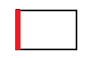
Now our customized board use TSC2046 as a touchscreen controller, and it already worked in our system, but it still existed an area  untouchable,  this area located on the left side of our screen, just like red part of below picture:

the related setting in DTS was listed as follow:

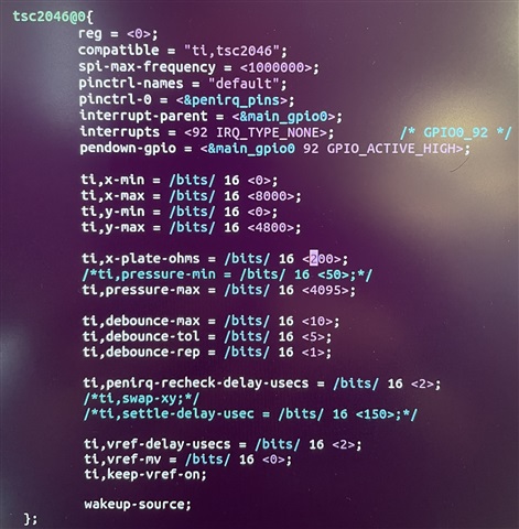
which parameters are the key to this untouchable area?

Thanks

Kenn

  • Hi Kenn,

    AGAIN I EXPECT THE AM6548 APPLICATIONS TEAM TO PROVIDE MORE INPUT BUT IN THE MEANTIME:

    Just an FYI to being, support may be somewhat limited on this question within this e2e forum given that it is for the TSC2046 Linux driver:  Hardware with that part is sometimes limited, we do not support specific Linux driver modifications on these forums, and in general the community maintains the driver instead of TI.

    That being said, can I first ask if you have first updated the latest TSC2046 driver per this related e2e thread?:

    https://e2e.ti.com/support/data-converters-group/data-converters/f/data-converters-forum/1081873/tsc2046-linux-driver?tisearch=e2e-sitesearch&keymatch=TSC2046#

    Also, your DTS appears consistent with many of the TSC2046 examples such as:

     tsc2046@0 {
            reg = <0>;    
            compatible = "ti,tsc2046";
            interrupt-parent = <&gpio3>;
            interrupts = <14 0>;    
            spi-max-frequency = <1000000>;
            pendown-gpio = <&gpio3 14 0>;

            ti,x-min = /bits/ 16 <0>;
            ti,x-max = /bits/ 16 <8000>;
            ti,y-min = /bits/ 16 <0>;
            ti,y-max = /bits/ 16 <4800>;
            ti,x-plate-ohms = /bits/ 16 <350>;
            ti,pressure-max = /bits/ 16 <255>;

    While I'm not initially suspecting the DTS itself of failure, the area you would consider changing is this specifically:

        ti,x-min = /bits/ 16 <>;
            ti,x-max = /bits/ 16 <>;
            ti,y-min = /bits/ 16 <>;
            ti,y-max = /bits/ 16 <>;

    Other online examples modify these min/max values accordingly, based on their implementations.

    However, since it appears to be a missing band aligned with the left-most region, a physical failure may be suspect.

    Does this behavior exhibit on another custom board in the same way?

    Are you sure you have a proper physical connection to the actually panel?

    Can you please check these and advise of your feedback?

    Thank you very much for your patience.

    Sincerely,

    Chris

  • Thanks Chris,

    We already fixed this problem.

    Thank you very much for your help!

    Kenn

  • Excellent, Kenn!  Nice work my friend !

    Regards,

    Chris