- Ask a related questionWhat is a related question?A related question is a question created from another question. When the related question is created, it will be automatically linked to the original question.

Original question:

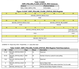
DRA821U: DRA821U: UDMA utilize OSPI access NorFlash configure read data length of every read command
Hello,
when I implemented DRA821 with Cypress NorFlash, we found following problem, I would appreciate it if you could help us with this problem, Thank you!
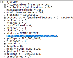
Fls failed to read&write with complete timeout issue. Fls config as below:
1. DRA821, NorFlash device is s28hs512t
2. Fls config as below:
CONST(struct Fls_ConfigType_s, FLS_CONFIG_DATA) FlsConfigSet =
{
.Fls_JobEndNotification = NULL_PTR,
.Fls_JobErrorNotification = NULL_PTR,
.maxReadNormalMode = 256U,
.maxWriteNormalMode = 256U,
.sectorList =
{
[0] =
{
.numberOfSectors = 256U,
.sectorPageSize = 256U,
.sectorSize = 262144U,
.sectorStartaddress = 1342177280U,
},
},
.dacEnable = FALSE,
.xipEnable = FALSE,
.ospiClkSpeed = 166666666U,
.dtrEnable = TRUE,
.phyEnable = FALSE,
};