This thread has been locked.

If you have a related question, please click the "Ask a related question" button in the top right corner. The newly created question will be automatically linked to this question.

PROCESSOR-SDK-AM62X: Generate PWM Signals on Am62x Timer4 in uboot

Part Number: PROCESSOR-SDK-AM62X
Other Parts Discussed in Thread: AM625

Hi,

I am trying to generate PWM output on Am62x Timer4 at u-boot. i have gone through some of the threads and added the code the u-boot.

https://e2e.ti.com/support/processors-group/processors/f/processors-forum/981809/am4378-how-to-configure-dm-timer4-as-pwm-output

But cant able to see any output on the Pin. pls guide me where i am going wrong.

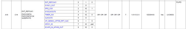
In Am62x SK Board, we have a  40 Pin Connector, where Pin number 7 can be configured as Timer4.

Configure the Pin to Timer 4.

__raw_writel(0x000000040x000F41F0);   /* Writing to the Pad register of Timer4 */   
Reading the frequency register of Timer4 shows that it is Default set to HFOSC0_CLKOUT
=> md.l 0x001081C0 1
001081c0: 00000000
#define TIMERIO4_TCLR (TIMERIO4_BASE + 0x38)
#define TIMERIO4_TLDR (TIMERIO4_BASE + 0x40)
#define TIMERIO4_TMAR (TIMERIO4_BASE + 0x4C)
#define TIMERIO4_TCRR (TIMERIO4_BASE + 0x3C)
#define TIMERIO4_TIOCP_CFG (TIMERIO4_BASE + 0x10)


#define COUNTER4_PERIOD (0xFFFFD120)                          /* Period : 1KHz */
#define COUNTER4_DUTY (0xFFFFE88F)                             /* Duty cycle : 50% */
#define PWM_CONFIG_TCLR (0x00001862)                          /* Setting in TCLR register : PT, TRG, TCM, SCPWM,CE, PRE, PTV, AR */
#define PWM_ENABLE_TCLR (0x00001863)                         /* Enable PWM timer : Setting ST bit */
void timer4_config(void)
{
__raw_writel(0X0000000 ,DMTIMER4_TCLR);                       // stop timer

while((__raw_readl(DMTIMER4_TCLR) & 0x00000001) !=0);

printf("Timer stop\n");

__raw_writel(PWM_CONFIG_TCLR ,DMTIMER4_TCLR); // Configuring the timer

__raw_writel(COUNTER4_PERIOD ,DMTIMER4_TLDR); // Setting period

__raw_writel(COUNTER4_PERIOD ,DMTIMER4_TCRR);

__raw_writel(0x08 ,DMTIMER4_TIOCP_CFG);

__raw_writel(COUNTER4_DUTY ,DMTIMER4_TMAR); // setting the duty cycle
}
And also i can't able to see any Timer nodes declared in k3-am62x-main.dtsi and k3-am625-sk.dts. 

Regards

Murali C

  • Hello,
    AM62x PWM is supported in Linux kernel
    software-dl.ti.com/.../PWM.html
    There's no support on PWM in u-boot as noted in the referenced e2e post.
    e2e.ti.com/.../am4378-how-to-configure-dm-timer4-as-pwm-output
    You may have to port it on your own.
    Best,
    -Hong

  • Hi Hong,

    Thanks for the reply.

    In our custom board which uses Am62x the Timer4 pin is connected to Watch Dog Timer Input. To test the Watch Dog timer at uboot. i need Timer Pulses on timer4 Pin.

    My Question is :

    On the Eval Board Am62xE1, We have a 40 Pin Connector, where Pin 7 can be configured as Timer 4(default is EXP_CLKOUT0).  if i configure this Pin as Timer 4. can i able to see any timer Pulses on the Pin.

    what are the changes i need to follow to get pulses on the Timer4 Pin. 

    I am probing the Timer4  signal through a Logic analyzer. 

    Kindly help me on this.

    Regards,

    Murali C 

  • Hello Murali,
    Let me loop in my colleague on HW/EVM on their input on your user case.
    Best,
    -Hong

  • Hello Murali C,

    Sorry for the delayed response.

    Please find your answers below:

    if i configure this Pin as Timer 4. can i able to see any timer Pulses on the Pin.

    Ans: Yes, this seems possible 

    what are the changes i need to follow to get pulses on the Timer4 Pin. 

    Ans:  To see any timer Pulses on the pin, it should be in Timer Mode.

    For PWM output at device pin, GPO_CFG should be 0X0. 

    Please refer the AM62 TRM for Timer PWM Mode Configuration under section 12.7.4.4.2.4 Timer PWM Mode

    Regards

    Rajashri

  • Hello Murali C,

    In the Eval Board Am62xE1, We have a 40 Pin Connector, where Pin 7 can be configured as Timer 4(default is EXP_CLKOUT0). 

    if i configure this Pin as Timer 4. can i able to see any timer Pulses on the Pin.

    From the hardware interface perspective, the pin had capability to be configured as a timer4. Pls refer below table. 

    what are the changes i need to follow to get pulses on the Timer4 Pin. 

    From the hardware perspective the pad configuration is required to be done

    Reference: Table 6-1. Pin Attributes (ALW, AMC Packages) (continued) of AM625 datasheet

    I am probing the Timer4 signal through a Logic analyzer. 

    I am not sure on the need for Logic analyzer. You should be able to probe with an oscilloscope.

    For implementing the pulse output, please refer 12.7 Timer Modules of the TRM 

    Regards,

    Sreenivasa