This thread has been locked.

If you have a related question, please click the "Ask a related question" button in the top right corner. The newly created question will be automatically linked to this question.

AM625: AM62X

Part Number: AM625
Other Parts Discussed in Thread: TPS22965, TPS65219

Hi , James ,

I also have AM62x can't boot up issue . The TPS6521903RHB didn't have the Power output .PMIC1.pdf

U4  pin 4,5,30,26 has VCC_3V3_MAIN power input ,but didnt have any Voltage outputs . When power on , the GP02 has a 20ms high plus output only  and RESETSTATz still keep low . 

  • Hello Jack Wang,

    Please verify and confirm all the supply voltage levels are as expected. you can measure on the bulk caps near the processor and PMIC.

    Pls try isolating R298.

    Regards

  • Dear Sreenivasa ,

    1. The attached is PMIC outputs' voltages which are correct .

    1351.PMIC3.pdf

    2. Also attached the current updated schematics .

    GW12.pdf

    3. Test some singles as below : a. PMIC_PGOOD  high

                                                       b. PMIC_PBn high

                                                       c.  RESETSTATz  Low

                                                       d. MCU_PORz High

                                                       e. PORz_OUT  low

                                                       f.MCU_RESETz high

                                                      h. SOC_WARM_RESETz high

                                                      g. Y2 & Y2 no clock outputs

                                                      i. U33 has 25Mhz output now.

    4. As I set first boot from SD card , however , RESETSTATz  also kept low not to enable SD power SW U13 on .

    Jack Wang

  • Typo :

    1. Y2 & Y3 no clock outputs
  • Hello Jack Wang,

    Thank you for the query.

    Y2 & Y3 no clock outputs

    The clocks have to be operational for processor to function. Are you using a X10 probe to measure the clock?

    Can you pls measure the supplies near to the SoC.

    Can you pls configure the SoC for external clock, disable the crystal and test.

    Pls expect delay in response for the next few days.

    Regards,

    Sreenivasa

  • Dear  Sreenivasa ,

    1. The clocks have to be operational for processor to function. Are you using a X10 probe to measure the clock?

        Yeah .

    2. Can you pls configure the SoC for external clock, disable the crystal and test.

    yeah , but took no effect , the PORz_OUT & RESETSTATz were still kept low .

    According to the spec. mentioned , MMCU_PORz , MCU_RESETz & Soc_WARM_RESETz are active high input to SOC , the PORz_OUT & RESETSTATz should be active high output , however , they are not .By the way , IO Expander is not yet programmed , how to control the  MMC1_SD_EN to enable SD card at the first time ? and  VPP_LO_EN is also the same . Should I program TCA6424ARGJR first ?

    IO expander.pdf

  • Hello Jack Wang,

    The core voltage should be 0.75. Not sure why you are measuring 0.8V. Could you please confirm. VDDR_core should measure 0.85.

    The clock should be functional if VDDS_OSC0 is supplies with VDDA_1V8

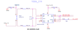
     Looks like VDDA1V8 from the PMIC is not getting translated to VDDA_1V8 on your board - net is a single net (in the EVM this was done through the shunt resistor as below)

    You may have to add a jumper.

    FYI the oscillator is powered by VCC_1V8 and, hence working.

    Regards,

    Sreenivasa

  • Hello Jack Wang,

    Please measure all the power supply rails required by the processor are available near to the processor rails by measuring supply across the bulk caps of decaps provided near each supply rail.

    This will help identify net name errors causing power supply rails to not be available.

    Regards,

    Sreenivasa

  • Hello Jack Wang,

    Did you get a chance to connect the VDDA_1V8 and perform some testing.

    Regards,

    Sreenivasa

  • Dear Sreenivsa ,

    After connectting the VDDA_1V8  , VDDS_OSC0  works with 25Mhz output , and  PORz_OUT & RESETSTATz are high . Also core voltage is 0.75V  .

    The next step is programming the system via SD card , as I mentioned how to program IO EXPANDER (TCA6424ARG) ?

    Jack Wang

  • Hello Jack Wang,

    Thank you for the inputs and good to hear the board is working.

    Could you measure the supply voltage near the SoC to be sure everything is functional.

    The next step is programming the system via SD card , as I mentioned how to program IO EXPANDER (TCA6424ARG) ?

    Do you have the SD card image ready.

    Do you have a EVM to test the image?

    For SD card boot the IO expander output has a pullup and i would expect the boor to work.

    Linux should take care of the IO configuration for normal operation. 

    Regards,

    Sreenivasa


  • Hello Jack Wang,

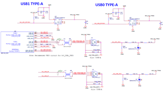
    As i reviewing the SD card interface, i observed that you have the USB type A connector but do not see 150uF cap near the USB 5V Vbus net.

    Please refer to the EVM and make sure you add that when you are testing the board for USB interface.

    Regards,

    Sreenivasa

  • Hello Jack Wang,

    The next step is programming the system via SD card , as I mentioned how to program IO EXPANDER (TCA6424ARG) ?

    Ad part of the design we recommend customer to add an isolation resistor (0R) for all the reset inputs controlled by the SoC GPIO and terminate the reset to enable condition.

    This help customer isolate GPIO while testing.

    Please note this and provision for the isolation resistors in the next version.

    Regards,

    Sreenivasa

  • Dear Sreenivasa ,

    ok , will add 150uF cap in next version .

    Jack Wang

  • Dear  Sreenivasa 

    Do you have the SD card image ready. 

    I use tisk-default-image (am62xx-evm-08,03,00,19 version) , however , it can't boot up , but I can see the COM port from MCU_UART0 by using FT234XD(U24) . 

    Do you have a EVM to test the image? yesh  , can work via tisk-default-image (am62xx-evm-08,03,00,19 version) .

    Jack Wang

  • Hello Jack Wang,

    Please check if the required supplies for the SD card interface is available.

    Regards,

    Sreenivasa

  • Hello Jack Wang,

    I checked with the design team and the IO expander configuration dependency is not there for the SD card to boot.

    Please compare with the EVM that works and ensure all the voltages and the terminations are available.

    I assume the SD card socket is similar to the EVM.

    I noticed that the ESD protection for the SD card has been removed. Please take note of the ESD related risk and provision for external ESD protection in the next revision.

    Regards,

    Sreenivasa


  • Dear Sreenivasa ,

    After  bootmode Bit 9 to set high , the boot up ok from SD card and with HDMI Screen output . Thanks for your supports in the past days , I will do more tests in the following  . The next version of PCB  will take into your suggests . Thanks again !

    Jack Wang

  • Hello Jack Wang,

    Good to hear the progress.

    I will close the thread.

    Regards,

    Sreenivasa