This thread has been locked.

If you have a related question, please click the "Ask a related question" button in the top right corner. The newly created question will be automatically linked to this question.

AM625: AM62X

Part Number: AM625
Other Parts Discussed in Thread: TPS22965, TPS65219

Hi , James ,

I also have AM62x can't boot up issue . The TPS6521903RHB didn't have the Power output .PMIC1.pdf

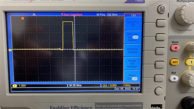
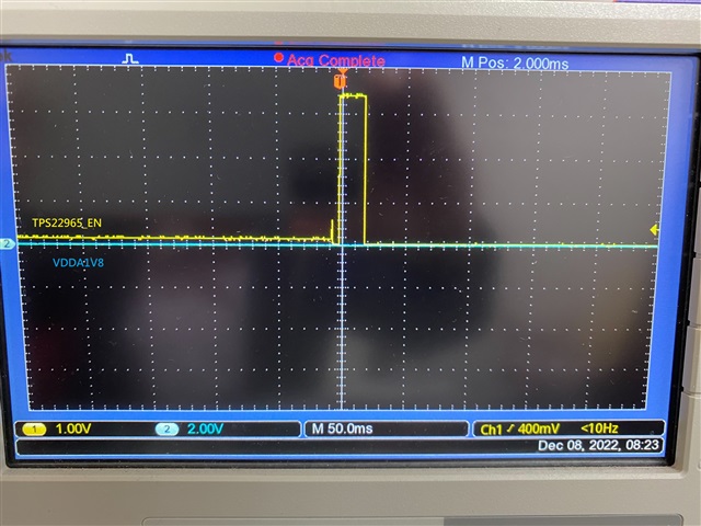
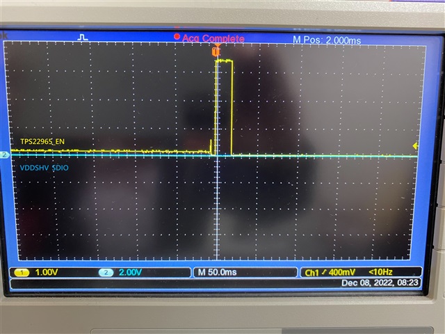
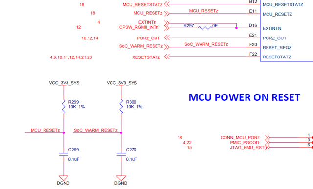
U4  pin 4,5,30,26 has VCC_3V3_MAIN power input ,but didnt have any Voltage outputs . When power on , the GP02 has a 20ms high plus output only  and RESETSTATz still keep low . 

  • Any one can answer my question  ?

  • Jack, the fact that RESETSTATz is low is a problem.  RESETSTATz is an output from the processor indicating that the MAIN domain is still in reset.  Can you provide the schematic portions with the MCU_PORz and other reset signals?  Can you probe MCU_PORz, RESET_REQz, PORz_OUT, MCU_RESETz?

    Regards,

    James

  • Dear JJd ,

    This is the first time power up , so the CPU core not yet programmed into . That is what I am wondering  how to make RESETSTATz active . Does the PMIC power outputs get disabled?AM62xx.pdf

  • Jack, no programming is needed on the CPU for RESETSTATz to go high.  It is dependent on the reset inputs i mentioned earlier and proper power to the device..  What is the state of these signals?  Can you check all of the power rails of the PMIC for proper voltage levels

    Regards,

    James

  • Dear James ,

    Please see the attachment with PMIC voltage outputs , also have measured those reset signals .

    1.MCU_RESETz 0.8V

    2. PORz_OUT 0.2V

    3.MCU_PORz 0V

    4. RESET_REQz 0.8V

    PMIC3.pdf

  • MCU_PORz is low, so you are still in reset.  It doesn't look like the PMIC is powering up properly since none of its outputs have voltages at the proper level.

    Check R203 and R206.  One of those should be DNI (as on the EVM schematic), otherwise you'll never get out of reset.

    Regards,

    James

  • Dear James ,

    Have removed R203 , but it is still got no effect . Any points ,shall I take care more?

    Jack Wang 

  • Ok, so is MCU_PORz still low?  If so, then need to check the signals that affect this.  Check:

    PMIC_PGOOD

    CONN_MCU_PORz

    JTAG_EMU_RSTz

    Also, what is the state of TPS22965_EN?  You show a 25ms pulse high, but the input to GPO2 you show 0V

    Regards,

    James

  • Dear James ,

    1. so is MCU_PORz still low?  Yes

    2. what is the state of TPS22965_EN?  You show a 25ms pulse high, but the input to GPO2 you show 0V , 

    Please see the attached file .

    Maybe , it is the key issue , TPS22965_EN can't be driven Hi to enable VCC_3V3_SYS Power .

    3.  

    a. PMIC_PGOOD      0V

    This has VCC_3V3_SYS pull up , but it kept 0V , seems like the PMIC drove it low .

    P.S.  VCC_3V3_SYS only 0.8V

    b. CONN_MCU_PORz 0.8V (by VCC_3V3_SYS pull up 0.8V)

    c. JTAG_EMU_RSTz  0.8V (by VCC_3V3_SYS pull up 0.8V)

    Jack Wang

  • Jack, i'm going to pass your question on to our PMIC group which handles the TPS65219.  It appears there is something wrong with this device since you are not getting any output power

    Regards,

    James

  • Dear James ,

    I  am also wondering if I got the right version of PMIC IC . Thanks for your help .

    Jack Wang

  • Hi Jack,

    Thanks for reaching out! Could you provide the full orderable part number for the PMIC? Could you also provide the power-up capture for the following signals:

    • VCC_3V3_MAIN
    • PMIC_PBn
    • VCC_3V3_SYS
    • VCC_1V8

    Thanks,

    Brenda

  • Dear Brenda ,

    1. PMIC orderable NO.  PTPS6521903RHBR

    2. Please see the attached files

    Jack Wang

  • Hi Jack, 

    Do you have any information of the shipment for those PMIC ICs? I would like to check internally if those devices were configured with the TPS6521903 NVM settings. Also, could you share a power-up scope capture that would include all the signals below in the same capture

    • GPO2
    • TPS22965_EN
    • VDDSHV_SDIO
    • VDDA1V8

    Thanks,

    Brenda  

  • Dear Brenda ,

    1. PMIC information please see the attached 


    2. GP02 & TPS22965_EN are the same signal . As my scope only has two channels , the power up scope are as below .

    the result , seems like GP02 only active for a short period of 25ms , I am wondering if  TPS6521903 didn't be configured with the NVM settings .

  • Hi Jack,

    Thanks for providing the shipping information and scope captures. We are reviewing those internally. In the meantime, are you seeing the same issue in more than one PCB? Have you tried replacing the PMIC with a brand new unit? 

    Thanks,

    Brenda

  • Dear Brenda ,

    1. I have checked more than 5 pcs of PCBA with the same issue . As I checked the PTPS6521903 A version seems like the first beginning one , what is the different between TPS6521903 ?

    2. I would like to replace it with brand new unit , would you send me 10 pcs ?

    Jack Wang

  • Dear Brenda ,

    Please check 

    2262.AM62xx.pdf

  • Dear Brenda ,

    Any feedback more ?

    Jack Wang

  • Hi Jack,

    Thanks for sharing the schematic! We are out of office on weekends but just started the week this morning so we will take a look at the schematic and provide an update within the next 24Hrs.  

    Thanks,

    Brenda

  • Dear Brenda ,

    How is the review for the schematics ? 

    Was  the sample version of PTPS6521903 configured for First Supply Detection (FSD) ?  if not , of course the PMIC shall not have any voltage outputs  (as PMIC Integrated voltage supervisor for undervoltage , here , PVIN_LDO2 is 0V ). According to the circuitry , the  PVIN_LDO2 uses  VCC_1V8 power source derived from LX_B2 , however , LX_B2 not output VCC_1V8 to cause the PMIC shout down . 

    Jack Wang

  • Hi Jack,

    We took a look at the schematic and from the PMIC perspective didn't identify any issues, it is almost identical to the Sitara EVM. I have send a private E2E with the instructions to request new PMIC samples. Regarding your question about FSD, this feature is enabled in the TPS6521903 NVM. 

    The Sitara processor team also reviewed the schematic and recommended to DNI the following resistors: R18 and R23. Could you try this and let me know if it makes a difference? 

    Thanks,

    Brenda

  • Dear Brenda ,

    After removing R18 & R23 , It got no effect  at all . Please see the attached file with pressing down the push down button SW1 for 4 seconds in wave .  . As I checked ,PVIN_LDO2 has no power VCC_1V8 voltage input when PMIC power on to cause the shut down . 

    Also , I have requested 20 pcs of TPS6521903 samples from Yang .

    Jack Wang

  • Hi Jack,

    We also noticed your design had all components populated and the Sitara EVM has some of the components as DNI. The processor team has added comments on all the components DNI that didn't match between the schematic you provided and the AM62 EVM design files.

    I have sent the full schematic with the comments through private message. Please let us know if you have any questions. 

    Thanks,

    Brenda

  • Dear Brenda ,

    Very thanks for your support , I will modify those errors . My design was based on PROC142E1 rev E1 , Could you send me the latest schematics of AM62 EVM ? 

    Jack Wang

  • Dear Brenda ,

    1. FL16 as DNP , it does'nt need the VCC_3V3_SYS power ?

    FL16.pdf

    2. R311 , R310 , R303  with pull up  resister , as the spec. mentioned not to leave it floating .

    R311.pdf

    3. R254 changes to 1% and configure it as DNP . It means not to use it why need to change to 1% ?

    R254.pdf

    Jack Wang

  • Hi Jack,

    I'm adding Sreenivasa from the Sitara processor team so he can comment on your questions.

    Thanks,

    Brenda

  • Hello Jack Wang, 

    Please refer below.

    1. FL16 as DNP , it does'nt need the VCC_3V3_SYS power ?

    Supply is not required to be connected and hence recomendation is to make it DNP

    . R311 , R310 , R303  with pull up  resister , as the spec. mentioned not to leave it floating .

    The value is 0R, please change to 4.7K or 10K whichever is available.

    R254 changes to 1% and configure it as DNP . It means not to use it why need to change to 1% ?

    Currently this is DNP. Since same resistor is used at 3 places, it it is a good practice to make it same 1% and DNP to avoid future errors.

    Regards,

    Sreenivasa

  • Hello Jack Wang, 

    I would suggest to prioritizing make changes on the PMIC, SoC and DDR that could cause the functional issue and try testing before making other peripheral changes.

    Regards,

    Sreenivasa

  • Hello Jack Wang, 

    I would want to bring to you notice the concerns having unused IOs pulled to the rail with a 0R.

    In the firmware i assume the unused IOs are configured as output. This is not a recommended use case and could cause device failures.

    Please make sure the pullup values are updated on the boards before you power up on high priority.

    Regards,

    Sreenivasa

  • Hello Jack Wang, 

    I see the below configuration for the Main and MCU warm reset.

    The RC is connected directly to the processor input.

    The slow ramp time will cause the Inputs to be in an undefined range during the ramp causing reliability issues.

    Please note this and make the required updates. You can follow the EVM as below.

    Regards,

    Sreenivasa

  • Hello Jack Wang, 

    Looks like the clock buffer was removde in the design.

    I assume the oscillator is placed near to the PHY.

    If not please add a buffer.

    Also, in the EVM the clock buffer supply had additional bulk caps placed near the clock buffer

    Please ensure these caps are placed near to the oscillator.

    Regards,

    Sreenivasa

  • Dear Sreenivasa ,

    Thanks for your Suggestions , i will make changes for those DNI components  first . However , my design was based on the schematics on PROC142E1-E 120220916 version which was the latest version then , now I need to change those are according to PROC142E1-E120220420 . It did make me confusion . Can you send me the latest one to me ?

    PROC14E1-E1 20220916.pdf

    PROC142E1-E120220420.pdf

  • Hello Jack Wang, 

    Thanks for your Suggestions , i will make changes for those DNI components  first . However , my design was based on the schematics on PROC142E1-E 120220916 version which was the latest version then , now I need to change those are according to PROC142E1-E120220420 . It did make me confusion . Can you send me the latest one to me ?

    The DNI is with respect to the version you are using. Please use the same version that you referenced and make sure the DNI in the reference schematics and the custom schematics you made match.

    As i mentioned, when you reuse the schematics and make any page change or sequence change the DNIs are no more enabled.

    Regards,

    Sreenivasa

  • Hello Jack Wang, 

    Did you have a chance to make the DNP updates specifically related to DDR and OSC0 and perform any test?

    Regards,

    Sreenivasa

  • Dear Sreenivasa ,

    As I was out of office those few days , will do those changes later on and inform you soon after the testing result .Thanks !

    Jack Wang

  • Hello Jack Wang, 

    Thank you for the note and appreciated.

    Regards,

    Sreenivasa

  • Dear  Sreenivasa ,

    Good news , the PMIC works well with the correct voltage outputs individually after changes . Thanks for your supports .

    The next step will make system boot from the SD card , however , the MMC1_SD_EN is controlled by IO EXPANDER TCA6424ARG , how can I program it  first in the beginning ? 

    Jack Wang

  • Hello Jack Wang, 

    Thank you for the inputs.

    Glad to hear the board is functional.

    The next step will make system boot from the SD card , however , the MMC1_SD_EN is controlled by IO EXPANDER TCA6424ARG , how can I program it  first in the beginning ? 

    Let me review this and update you.

    Regards,

    Sreenivasa

  • Dear Streenivasa ,

    By the way ,  RESETSTARTz & PORz_OUT are always in LOW stage .

    Jack Wang

  • Hello Jack Wang,

    The next step will make system boot from the SD card , however , the MMC1_SD_EN is controlled by IO EXPANDER TCA6424ARG , how can I program it  first in the beginning ? 

    I reviewed the EVM and looks like the configuration is similar.

    Have you tried configuring the SD card boot. I assume this should work.

    Please refer the EVM user guide for configuring the boptmode if you use EVM or the TRM for set the configuration on the custom board.

    Regards,

    Sreenivasa

  • Hello Jack Wang,

    Please check TP11 and TP55.

    These should be high.

    Regards,

    Sreenivasa

  • Dear Sreenivasa ,

    TP11 PMIC_PGOOD  is high , however , didnt find TP55 . What is the signal name ?

    Jack Wang

  • Hello Jack Wang,

    This is a typo.

    Please check for TP51 MCU_PORZ., 1.8V output.

    There was an error in the oscillator configuration. Xo was being grounded through a 0R R239 resistor, this has to be made DNI. Please check if the oscillator works.

    Regards,

    Sreenivasa

  • Dear Sreenivasa ,

    TP51 MCU_PORZ. with 1.8V output, however , X0 oscillator (Y3) doesn't work after removing  0R R239 out .

    Jack Wang

  • Hello Jack Wang,

    Can you please check CLKOUT_OSC output. Could you tap the clock output and connect to the Xi input and populate R239.

    DNI R237 and R238 and test. We are changing the oscillator mode from crystal to oscillator to test.

    Regards,

    Sreenivasa

  • Hello Jack Wang,

    Do you have a board that was not powered with DNI components mounted.

    Regards,

    Sreenivasa

  • Dear Streenivasa ,

    1. As CLKOUT_OSC output is low from  U33 OSC, U33 pin 4 has 1.8V and pin1 is high , I am checking this issue  so can't use it to drive the Xi input now  .

    2. Y3 pin 1 and Pin 3 are low , also Y2 (32.768khz) Pin 1 & Pin 2 are low ,when the system is in the very beginning not being programmed yet , can they work ? 

  • Dear Sreenivasa ,

    I am sorry . What did you mean ?

    Jack Wang

  • Hello Jack Wang,

    I was checking if all the boards you had was turned on with all the DNP components mounted?

    Regards,

    Sreenivasa

1 2