This thread has been locked.
If you have a related question, please click the "Ask a related question" button in the top right corner. The newly created question will be automatically linked to this question.
Hi TI experts,
The mesh lut files was generated follow the step of the case [FAQ] TDA4VM: How to create a LDC mesh LUT for fisheye distortion correction on TDA4?, however, I found that the output image of LDC has one problem, the last line of the image is messy green, as shown in figure below:
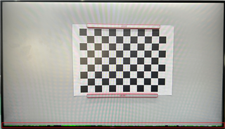
do you know what cause this?
another question is that the YUV image saved by DCC is not processed by LDC, is that normal?
The xml file is attached here for check:
<?xml version="1.0" encoding="utf-8"?> <cfg_ldc_xml xmlns:xsi="http://www.w3.org/2001/xmlschema-instance" xmlns:xsd="http://www.w3.org/2001/xmlschema"> <!--this is a comment--> <dcc_name>cfg_ldc</dcc_name> <dcc_header> <camera_module_id> 233 </camera_module_id> <dcc_descriptor_id> 5 </dcc_descriptor_id> <algorithm_vendor_id> 1 </algorithm_vendor_id> <tunning_tool_version> 0 </tunning_tool_version> </dcc_header> <!--=======================================================================--> <typedef> <cfg_ldc_vars type="struct"> <ldc_en type="uint16"> </ldc_en> <ldc_ldmapen type="uint16"> </ldc_ldmapen> <ldc_datamode type="uint16"> </ldc_datamode> <ldc_opdatamode type="uint16"> </ldc_opdatamode> <ldc_ip_dfmt type="uint16"> </ldc_ip_dfmt> <ldc_pwarpen type="uint16"> </ldc_pwarpen> <ldc_yint_typ type="uint16"> </ldc_yint_typ> <ldc_regmode_en type="uint16"> </ldc_regmode_en> <ldc_meshtable_m type="uint16"> </ldc_meshtable_m> <ldc_mesh_frsz_w type="uint16"> </ldc_mesh_frsz_w> <ldc_mesh_frsz_h type="uint16"> </ldc_mesh_frsz_h> <ldc_compute_frsz_w type="uint16"> </ldc_compute_frsz_w> <ldc_compute_frsz_h type="uint16"> </ldc_compute_frsz_h> <ldc_initx type="uint16"> </ldc_initx> <ldc_inity type="uint16"> </ldc_inity> <ldc_input_frsz_w type="uint16"> </ldc_input_frsz_w> <ldc_input_frsz_h type="uint16"> </ldc_input_frsz_h> <ldc_obw type="uint16"> </ldc_obw> <ldc_obh type="uint16"> </ldc_obh> <ldc_pixpad type="uint16"> </ldc_pixpad> <ldc_a type="int16"> </ldc_a> <ldc_b type="int16"> </ldc_b> <ldc_c type="int16"> </ldc_c> <ldc_d type="int16"> </ldc_d> <ldc_e type="int16"> </ldc_e> <ldc_f type="int16"> </ldc_f> <ldc_g type="int16"> </ldc_g> <ldc_h type="int16"> </ldc_h> <ldc_sf_width type="uint16[3]"> </ldc_sf_width> <ldc_sf_height type="uint16[3]"> </ldc_sf_height> <ldc_sf_en type="uint16[3][3]"> </ldc_sf_en> <ldc_sf_obw type="uint16[3][3]"> </ldc_sf_obw> <ldc_sf_obh type="uint16[3][3]"> </ldc_sf_obh> <ldc_sf_pad type="uint16[3][3]"> </ldc_sf_pad> <ldc_ylut_en type="uint16"> </ldc_ylut_en> <ldc_yin_bitdpth type="uint16"> </ldc_yin_bitdpth> <ldc_yout_bitdpth type="uint16"> </ldc_yout_bitdpth> <ldc_clut_en type="uint16"> </ldc_clut_en> <ldc_cin_bitdpth type="uint16"> </ldc_cin_bitdpth> <ldc_cout_bitdpth type="uint16"> </ldc_cout_bitdpth> <ldc_y_lut type="uint16[513]"> </ldc_y_lut> <ldc_c_lut type="uint16[513]"> </ldc_c_lut> <mesh_table_pitch_in_bytes type="uint32"> </mesh_table_pitch_in_bytes> <mesh_table_size type="uint32"> </mesh_table_size> <mesh_lut type="uint16*"> </mesh_lut> </cfg_ldc_vars> </typedef> <!--=======================================================================--> <use_case val="65535"> <n-space> <region0 class="0"> <exposure val="1" min="0" max="2000000"> </exposure> <gain val="0" min="0" max="100000"> </gain> </region0> </n-space> <parameter_package> <ldc_dcc type="cfg_ldc_vars"> { 1 // LDC_CTRL LDC_EN(0) LDC Enable, 0: Disable, 1: Enable 1 // LDC_CTRL LDMAPEN(1) LD Mapping enable, 0: disable, 1: enable 2 // LDC_CTRL DATAMODE(4:3) Input data mode, 0: YUV422, 1: Y only, 2: YUV420, 3: YUV420 UV 0 // LDC_CTRL OP_DATAMODE Output data mode, 0: keep UYVY; 1: convert to 420 0 // LDC_CTRL IP_DFMT(6:5) Input pixel format, 0: 8b, 1: 12b packed, 2: 12b unpacked 1 // LDC_CTRL PWARPEN(7) 0: Disable perspective warp. 1: Enable perspective warp 0 // LDC_CFG YINT_TYP(6) Interpolation type for Y data. 0: Bicubic, 1: Bilinear 0 // LDC_CFG REGMODE_EN Region mode, 0: disable, 1: enable 4 // LDC_MESHTABLE_CFG M(2:0) Mesh table subsampling factor (0-7) 1920 // LDC_MESH_FRSZ W(13:0) Mesh frame width (0-8192) 1080 // LDC_MESH_FRSZ H(29:16) Mesh frame height (0-8192) 1920 // LDC_COMPUTE_FRSZ W(13:0) Compute width (0-8192) 1080 // LDC_COMPUTE_FRSZ H(29:16) Compute height (0-8192) 0 // LDC_INITXY INITX(13:0) Output starting horizontal coordinate (0-8192) 0 // LDC_INITXY INITY(29:16) Output starting vertical coordinate (0-8192) 1920 // LDC_INPUT_FRSZ W(29:16) Input frame width 1080 // LDC_INPUT_FRSZ H(13:0) Input frame height 128 // LDC_BLOCK_SIZE OBW(7:0) Output block width (0-255) 16 // LDC_BLOCK_SIZE OBH(15:8) Output block height (0-255) 1 // LDC_BLOCK_SIZE PIXPAD(19:16) Pixel pad (0-15) 4096 // LDC_AB A(15:0) Affine Transform warp, A S16Q12 0 // LDC_AB B(31:16) Affine Transform warp, B S16Q12 0 // LDC_CD C(15:0) Affine Transform warp, C S16Q3 0 // LDC_CD D(31:16) Affine Transform warp, D S16Q12 4096 // LDC_EF E(15:0) Affine Transform warp, E S16Q12 0 // LDC_EF F(31:16) Affine Transform warp, F S16Q3 0 // LDC_GH G(15:0) Affine Transform warp, G S16Q23 0 // LDC_GH H(31:16) Affine Transform warp, H S16Q23 {0, 0, 0} //ldc_sf_width [3] {0, 0, 0} //ldc_sf_height[3] {{0, 0, 0}, {0, 0, 0}, {0, 0, 0}} //ldc_sf_en [3][3] {{0, 0, 0}, {0, 0, 0}, {0, 0, 0}} //ldc_sf_obw[3][3] {{0, 0, 0}, {0, 0, 0}, {0, 0, 0}} //ldc_sf_obh[3][3] {{0, 0, 0}, {0, 0, 0}, {0, 0, 0}} //ldc_sf_pad[3][3] 0 // LDC_DUALOUT_CFG YLUT_EN Luma LUT enable (0-1) 8 // LDC_DUALOUT_CFG YIN_BITDPTH Luma input bit depth (8-12) 8 // LDC_DUALOUT_CFG YOUT_BITDPTH Luma output bit depth (8-12) 0 // LDC_DUALOUT_CFG CLUT_EN Chroma LUT enable (0-1) 8 // LDC_DUALOUT_CFG CIN_BITDPTH Chroma input bit depth (8-12) 8 // LDC_DUALOUT_CFG COUT_BITDPTH Chroma output bit depth (8-12) { //y_lut 0,0,0,0,0,0,0,0,0,0,0,0,0,0,0,0,0,0,0,0,0,0,0,0,0,0,0,0,0,0,0,0,0,0,0,0,0,0,0,0,0,0,0,0,0,0,0,0,0,0,0,0,0,0,0,0,0,0,0,0,0,0,0,0,0,0,0,0,0,0,0,0,0,0,0,0,0,0,0,0,0,0,0,0,0,0,0,0,0,0,0,0,0,0,0,0,0,0,0,0,0,0,0,0,0,0,0,0,0,0,0,0,0,0,0,0,0,0,0,0,0,0,0,0,0,0,0,0,0,0,0,0,0,0,0,0,0,0,0,0,0,0,0,0,0,0,0,0,0,0,0,0,0,0,0,0,0,0,0,0,0,0,0,0,0,0,0,0,0,0,0,0,0,0,0,0,0,0,0,0,0,0,0,0,0,0,0,0,0,0,0,0,0,0,0,0,0,0,0,0,0,0,0,0,0,0,0,0,0,0,0,0,0,0,0,0,0,0,0,0,0,0,0,0,0,0,0,0,0,0,0,0,0,0,0,0,0,0,0,0,0,0,0,0,0,0,0,0,0,0,0,0,0,0,0,0,0,0,0,0,0,0,0,0,0,0,0,0,0,0,0,0,0,0,0,0,0,0,0,0,0,0,0,0,0,0,0,0,0,0,0,0,0,0,0,0,0,0,0,0,0,0,0,0,0,0,0,0,0,0,0,0,0,0,0,0,0,0,0,0,0,0,0,0,0,0,0,0,0,0,0,0,0,0,0,0,0,0,0,0,0,0,0,0,0,0,0,0,0,0,0,0,0,0,0,0,0,0,0,0,0,0,0,0,0,0,0,0,0,0,0,0,0,0,0,0,0,0,0,0,0,0,0,0,0,0,0,0,0,0,0,0,0,0,0,0,0,0,0,0,0,0,0,0,0,0,0,0,0,0,0,0,0,0,0,0,0,0,0,0,0,0,0,0,0,0,0,0,0,0,0,0,0,0,0,0,0,0,0,0,0,0,0,0,0,0,0,0,0,0,0,0,0,0,0,0,0,0,0,0,0,0,0,0,0,0,0,0,0,0,0,0,0,0,0,0,0,0,0,0,0,0,0,0,0,0,0,0,0,0,0,0,0,0,0,0,0,0,0,0,0,0,0,0,0,0,0,0,0,0,0,0,0 } { //c_lut 0,0,0,0,0,0,0,0,0,0,0,0,0,0,0,0,0,0,0,0,0,0,0,0,0,0,0,0,0,0,0,0,0,0,0,0,0,0,0,0,0,0,0,0,0,0,0,0,0,0,0,0,0,0,0,0,0,0,0,0,0,0,0,0,0,0,0,0,0,0,0,0,0,0,0,0,0,0,0,0,0,0,0,0,0,0,0,0,0,0,0,0,0,0,0,0,0,0,0,0,0,0,0,0,0,0,0,0,0,0,0,0,0,0,0,0,0,0,0,0,0,0,0,0,0,0,0,0,0,0,0,0,0,0,0,0,0,0,0,0,0,0,0,0,0,0,0,0,0,0,0,0,0,0,0,0,0,0,0,0,0,0,0,0,0,0,0,0,0,0,0,0,0,0,0,0,0,0,0,0,0,0,0,0,0,0,0,0,0,0,0,0,0,0,0,0,0,0,0,0,0,0,0,0,0,0,0,0,0,0,0,0,0,0,0,0,0,0,0,0,0,0,0,0,0,0,0,0,0,0,0,0,0,0,0,0,0,0,0,0,0,0,0,0,0,0,0,0,0,0,0,0,0,0,0,0,0,0,0,0,0,0,0,0,0,0,0,0,0,0,0,0,0,0,0,0,0,0,0,0,0,0,0,0,0,0,0,0,0,0,0,0,0,0,0,0,0,0,0,0,0,0,0,0,0,0,0,0,0,0,0,0,0,0,0,0,0,0,0,0,0,0,0,0,0,0,0,0,0,0,0,0,0,0,0,0,0,0,0,0,0,0,0,0,0,0,0,0,0,0,0,0,0,0,0,0,0,0,0,0,0,0,0,0,0,0,0,0,0,0,0,0,0,0,0,0,0,0,0,0,0,0,0,0,0,0,0,0,0,0,0,0,0,0,0,0,0,0,0,0,0,0,0,0,0,0,0,0,0,0,0,0,0,0,0,0,0,0,0,0,0,0,0,0,0,0,0,0,0,0,0,0,0,0,0,0,0,0,0,0,0,0,0,0,0,0,0,0,0,0,0,0,0,0,0,0,0,0,0,0,0,0,0,0,0,0,0,0,0,0,0,0,0,0,0,0,0,0,0,0,0,0,0,0,0,0,0,0,0,0,0,0,0,0,0,0,0,0,0,0,0,0,0,0,0,0,0,0,0,0,0,0,0 } 496, //mesh_table_pitch_in_bytes 17112, //mesh_table_size { //mesh_lut #include "OVX3C-MAX9295_MARS_mesh_lut.txt" } } </ldc_dcc> </parameter_package> </use_case> <!--=====================================================================--> </cfg_ldc_xml>
Hi Zhili,
It is very likely caused by a bug we fixed in the upcoming V3.0.
The LUT file should have 69 rows rather than 68.
While generating the LUT file, tuning tool does not write out the last row properly to the text file.
We typically use larger mesh frame size than output image size and therefore we did not see that issue while releasing V2.5.
To get around, you may do it again with image height 1096 to get a new LUT with 69 rows to replace your current LUT file.
If you share your LDC tuning project, I can try it out on my side with the bug fixed version to confirm.
Hi Gang,
After changed the image height to 1096, the messy green in the last lines of LDC output image is gone.
The lens distortion spec file, matlalb code and YUV image is attached here:
I cannot save YUV image with LDC successfull, the images saved still not processed by lens distortion correction, what's reason of this?
By the way, when will DCC V3.0 be released?
Thanks.
Hi Zhili,
Thanks for the update!
That confirms the cause is as we suspected.
>> I cannot save YUV image with LDC
I suppose you mean save LDC output from H/W using the tuning tool.
I don't think that is supported.
The YUV image transferred from H/W to tuning tool is the VISS output (before LDC).
Can you provide me a dowmload link? Or do I need to contact local TI FAE to get?