We are using one of the PRUs within the AM6548 to generate PWM signals using IEP compare timers. We are noticing occasional timing excursions with the global counter. Since this is used to generate the start of a 200 Hz frame on which the PWM signals are started, it has the effect of causing their timing to be off as well.
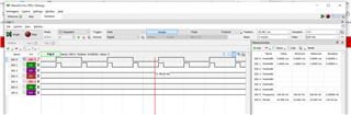
Our test configuration includes two GPIO lines attached to an oscilloscope, the first of which is used to measure the start of the PWM frame, the second is a one of the actual PWM channels.
The TRM mentions a compensation and slow compensation register but no real meaningful explanation of what they are and how they should be used which makes us unsure if they even apply here.
Has anyone else experienced this or can provide some guidance for further testing?
Thanks in advance,
Mike
#include <stdint.h>
#include <pru_cfg.h>
#include <pru_iep.h>
#include "rsc_table_pwm.h"

// Calculated global counter value (0xffffffff - 1,250,000) [250MHz / 200Hz]
#define COUNT_REG0_200HZ        0xffeced2f

// Adjusted counter value based on physical measurements
//#define COUNT_REG0_200HZ        0xffeced32
#define COUNT_REG1_200HZ        0xffffffff

#define CHANNEL1_BIT            (1 << 4)
#define CHANNEL2_BIT            (1 << 16)

#define CYCLES_PER_US           250

volatile register uint32_t __R30;

void main()
{
    register uint32_t r30Val = 0;
    int state = 0;
    register uint32_t channel2CmpValue = COUNT_REG0_200HZ + (1000 * CYCLES_PER_US);

    CT_CFG.gpcfg0_reg = 0;

    // Setup compare timers (AM65x TRM Section 6.5.13.2.4)
    CT_CFG.cgr_reg_bit.iep_clk_en = 1;

    // Disable counter
    CT_IEP0.global_cfg_reg_bit.cnt_enable = 0;

    // Clear counter registers
    CT_IEP0.count_reg0 = 0xffffffff;
    CT_IEP0.count_reg1 = 0xffffffff;

    // Set count registers
    CT_IEP0.count_reg0 = COUNT_REG0_200HZ;
    CT_IEP0.count_reg1 = COUNT_REG1_200HZ;

    // Clear overflow status register
    CT_IEP0.global_status_reg_bit.cnt_ovf = 1;

    // Clear compare status register
    CT_IEP0.cmp_status_reg = 0xffffffff;

    // Set counter increment value
    CT_IEP0.global_cfg_reg_bit.default_inc = 1;

    // Enable counter
    CT_IEP0.global_cfg_reg_bit.cnt_enable = 1;

    while (1)
    {
        __R30 = r30Val;

        // Start of pwm frame if global counter has overflowed
        if (CT_IEP0.global_status_reg_bit.cnt_ovf)
        {
            // Reset count registers
            CT_IEP0.count_reg0 = COUNT_REG0_200HZ;
            CT_IEP0.count_reg1 = COUNT_REG1_200HZ;

            // Clear compare status register
            CT_IEP0.cmp_status_reg = 0xffffffff;

            // Generate square wave for verifying global counter timing and frequency
            if (state)
                r30Val |= CHANNEL1_BIT;
            else
                r30Val &= ~CHANNEL1_BIT;

            state = !state;

            // Turn on channel 2
            r30Val |= CHANNEL2_BIT;

            // Set compare register for channel 2
            CT_IEP0.cmp0_reg0 = channel2CmpValue;
            CT_IEP0.cmp0_reg1 = COUNT_REG1_200HZ;

            // Enable compare events for channel 2
            CT_IEP0.cmp_cfg_reg_bit.cmp_en = 0x000000001;

            // Reset overflow flag
            CT_IEP0.global_status_reg_bit.cnt_ovf = 1;
        }
        else
        {
            // Turn off channel 2 if its compare register has expired
            if (CT_IEP0.cmp_status_reg_bit.cmp_status & (1 << 0)) {
                r30Val &= ~CHANNEL2_BIT;
            }
        }

    }

}