This thread has been locked.

If you have a related question, please click the "Ask a related question" button in the top right corner. The newly created question will be automatically linked to this question.

AM620-Q1: DDR implementation

Part Number: AM620-Q1

Hello, 

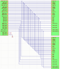
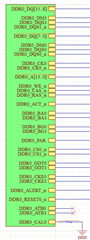
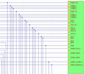
Referring to the AM620x DDR design guide https://www.ti.com/lit/an/sprad06/sprad06.pdf I come across this screenshot showing one 16 bit DDR connection to the microprocessor. In it, the DDR0_BG1, DDR0_CS1, DDR0_ODT1, and DDR0_CKE1 pins are No Connects.  

Does TI see a reason why there cant be a second DDR interface connected to those No Connect lines mentioned above? All other signal lines shown would be shared between the two devices. 

  • Seth, most of those signals support connection to a second rank.  And if you use devices with x8 die, you would need to use the BG1 signal.  So there are examples which would use those signals, we just don't have that example portrayed in the app note.  One point to make is that the data bus should be routed as point to point.

    Regards,

    James    

  • Hi James, 

    I had forgotten to mention that the second DDR interface that I would try to interface to would also be x16 not two x8. This is how I was envisioning the signals to be connected. 

    Here is the reason for my original confusion and is why I came to the forum to discuss.

    In section 9.1 of the Technical Reference Manual indicates that the DDRSS can support Up to 2 ranks.

    This would seem to contradict Table 2-1. Supported DDR4 SDRAM Combinations in the DDR Board Design and Layout Guidelines that indicates that you can only have a single x16 SDRAM.  However, I believe this is meant as the possible combinations on a single rank rather than the total number of devices that can be supported.

    So, is only one x16 DDR device supported, or can two x16 devices be connected like shown above? 

    Thanks!

    If you cannot see the signal names here are the zoomed in screenshots. 

    Top left - 

    Top right - 

    Bottom right - 

  • Seth, your schematics are showing a split data and address bus in T-topology, which is not supported.  If you have multiple DDR4 devices on the board, you would need to connect in fly-by topology, and even then, they would need to be x8 devices to meet the requirement that the data bus is point to point.  The app note has an example schematic of using two x8 devices in fly by (single rank), or you can use something like MT40A2G8 (as an example) to connect as a dual rank.

    Regards,

    James