This thread has been locked.
If you have a related question, please click the "Ask a related question" button in the top right corner. The newly created question will be automatically linked to this question.
Hi, I apply hardware and software modification according to : [FAQ] TDA4VM: TDA4VM/DRA829V: routing PCIE reference clock externally - Processors forum - Processors - TI E2E support forums, but no clk detected.
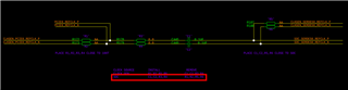
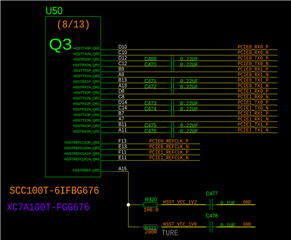
we are using sdk8.6 with EVM - TDA4VM and the modifications we make to the hardware are:
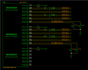
The clock selection scheme is as follows:
The EP device on the opposite end is an FPGA platform and is ready for use
Related content about PCIe in the device tree
// arch/arm64/boot/dts/ti/k3-j721e-main.dtsi pcie0_rc: pcie@2900000 { compatible = "ti,j721e-pcie-host"; reg = <0x00 0x02900000 0x00 0x1000>, <0x00 0x02907000 0x00 0x400>, <0x00 0x0d000000 0x00 0x00800000>, <0x00 0x10000000 0x00 0x00001000>; reg-names = "intd_cfg", "user_cfg", "reg", "cfg"; interrupt-names = "link_state"; interrupts = <GIC_SPI 318 IRQ_TYPE_EDGE_RISING>; device_type = "pci"; ti,syscon-pcie-ctrl = <&scm_conf 0x4070>; max-link-speed = <3>; num-lanes = <2>; power-domains = <&k3_pds 239 TI_SCI_PD_EXCLUSIVE>; clocks = <&k3_clks 239 1>; clock-names = "fck"; #address-cells = <3>; #size-cells = <2>; bus-range = <0x0 0xff>; vendor-id = <0x104c>; device-id = <0xb00d>; msi-map = <0x0 &gic_its 0x0 0x10000>; dma-coherent; ranges = <0x01000000 0x0 0x10001000 0x0 0x10001000 0x0 0x0010000>, <0x02000000 0x0 0x10011000 0x0 0x10011000 0x0 0x7fef000>; dma-ranges = <0x02000000 0x0 0x0 0x0 0x0 0x10000 0x0>; #interrupt-cells = <1>; interrupt-map-mask = <0 0 0 7>; interrupt-map = <0 0 0 1 &pcie0_intc 0>, /* INT A */ <0 0 0 2 &pcie0_intc 0>, /* INT B */ <0 0 0 3 &pcie0_intc 0>, /* INT C */ <0 0 0 4 &pcie0_intc 0>; /* INT D */ pcie0_intc: interrupt-controller { interrupt-controller; #interrupt-cells = <1>; interrupt-parent = <&gic500>; interrupts = <GIC_SPI 312 IRQ_TYPE_EDGE_RISING>; }; }; // arch/arm64/boot/dts/ti/k3-j721e-common-proc-board.dts pcie1_rc: pcie@2910000 { compatible = "ti,j721e-pcie-host"; reg = <0x00 0x02910000 0x00 0x1000>, <0x00 0x02917000 0x00 0x400>, <0x00 0x0d800000 0x00 0x00800000>, <0x00 0x18000000 0x00 0x00001000>; reg-names = "intd_cfg", "user_cfg", "reg", "cfg"; interrupt-names = "link_state"; interrupts = <GIC_SPI 330 IRQ_TYPE_EDGE_RISING>; device_type = "pci"; ti,syscon-pcie-ctrl = <&scm_conf 0x4074>; max-link-speed = <3>; num-lanes = <2>; power-domains = <&k3_pds 240 TI_SCI_PD_EXCLUSIVE>; clocks = <&k3_clks 240 1>; clock-names = "fck"; #address-cells = <3>; #size-cells = <2>; bus-range = <0x0 0xff>; vendor-id = <0x104c>; device-id = <0xb00d>; msi-map = <0x0 &gic_its 0x10000 0x10000>; dma-coherent; ranges = <0x01000000 0x0 0x18001000 0x0 0x18001000 0x0 0x0010000>, <0x02000000 0x0 0x18011000 0x0 0x18011000 0x0 0x7fef000>; dma-ranges = <0x02000000 0x0 0x0 0x0 0x0 0x10000 0x0>; #interrupt-cells = <1>; interrupt-map-mask = <0 0 0 7>; interrupt-map = <0 0 0 1 &pcie1_intc 0>, /* INT A */ <0 0 0 2 &pcie1_intc 0>, /* INT B */ <0 0 0 3 &pcie1_intc 0>, /* INT C */ <0 0 0 4 &pcie1_intc 0>; /* INT D */ pcie1_intc: interrupt-controller { interrupt-controller; #interrupt-cells = <2>; interrupt-parent = <&gic500>; interrupts = <GIC_SPI 324 IRQ_TYPE_EDGE_RISING>; }; }; &serdes_ln_ctrl { idle-states = <J721E_SERDES0_LANE0_PCIE0_LANE0>, <J721E_SERDES0_LANE1_PCIE0_LANE1>, <J721E_SERDES1_LANE0_PCIE1_LANE0>, <J721E_SERDES1_LANE1_PCIE1_LANE1>, <J721E_SERDES2_LANE0_IP1_UNUSED>, <J721E_SERDES2_LANE1_USB3_1>, <J721E_SERDES3_LANE0_USB3_0_SWAP>, <J721E_SERDES3_LANE1_USB3_0>, <J721E_SERDES4_LANE0_EDP_LANE0>, <J721E_SERDES4_LANE1_EDP_LANE1>, <J721E_SERDES4_LANE2_EDP_LANE2>, <J721E_SERDES4_LANE3_EDP_LANE3>; }; &serdes0 { serdes0_pcie_link: phy@0 { reg = <0>; cdns,num-lanes = <2>; #phy-cells = <0>; cdns,phy-type = <PHY_TYPE_PCIE>; resets = <&serdes_wiz0 1>; }; }; &serdes0 { status = "okay"; }; &serdes1 { serdes1_pcie_link: phy@0 { reg = <0>; cdns,num-lanes = <2>; #phy-cells = <0>; cdns,phy-type = <PHY_TYPE_PCIE>; resets = <&serdes_wiz1 1>, <&serdes_wiz1 2>; }; }; &serdes1 { status = "okay"; }; &pcie0_rc { pinctrl-names = "default"; pinctrl-0 = <&ekey_reset_pins_default>; reset-gpios = <&main_gpio0 72 GPIO_ACTIVE_HIGH>; clocks = <&k3_clks 239 1>, <&serdes0 CDNS_SIERRA_DERIVED_REFCLK>; clock-names = "fck", "pcie_refclk"; phys = <&serdes0_pcie_link>; phy-names = "pcie-phy"; num-lanes = <2>; }; &pcie1_rc { pinctrl-names = "default"; pinctrl-0 = <&mkey_reset_pins_default>; reset-gpios = <&wkup_gpio0 11 GPIO_ACTIVE_HIGH>; clocks = <&k3_clks 240 1>, <&serdes1 CDNS_SIERRA_DERIVED_REFCLK>; clock-names = "fck", "pcie_refclk"; phys = <&serdes1_pcie_link>; phy-names = "pcie-phy"; num-lanes = <2>; };
dmesg log are normal, but we do not see linkup log...
root@tda4vm-sk:~# dmesg|grep pci [ 1.258506] j721e-pcie 2900000.pcie: host bridge /bus@100000/pcie@2900000 ranges: [ 1.266178] j721e-pcie 2900000.pcie: IO 0x0010001000..0x0010010fff -> 0x0010001000 [ 1.274455] j721e-pcie 2900000.pcie: MEM 0x0010011000..0x0017ffffff -> 0x0010011000 [ 1.282732] j721e-pcie 2900000.pcie: IB MEM 0x0000000000..0xffffffffffff -> 0x0000000000 [ 1.291653] j721e-pcie 2910000.pcie: host bridge /bus@100000/pcie@2910000 ranges: [ 1.299337] j721e-pcie 2910000.pcie: IO 0x0018001000..0x0018010fff -> 0x0018001000 [ 1.307613] j721e-pcie 2910000.pcie: MEM 0x0018011000..0x001fffffff -> 0x0018011000 [ 1.315895] j721e-pcie 2910000.pcie: IB MEM 0x0000000000..0xffffffffffff -> 0x0000000000 [ 1.873071] j721e-pcie 2900000.pcie: host bridge /bus@100000/pcie@2900000 ranges: [ 1.880620] j721e-pcie 2900000.pcie: IO 0x0010001000..0x0010010fff -> 0x0010001000 [ 1.888752] j721e-pcie 2900000.pcie: MEM 0x0010011000..0x0017ffffff -> 0x0010011000 [ 1.896885] j721e-pcie 2900000.pcie: IB MEM 0x0000000000..0xffffffffffff -> 0x0000000000 [ 1.907327] CXY ######## PCIE j721e_pcie_probe:655 ret:[0] [ 1.912803] CXY ######## PCIE j721e_pcie_probe:669 ret:[0] [ 2.912740] j721e-pcie 2900000.pcie: PCI host bridge to bus 0000:00 [ 2.919007] pci_bus 0000:00: root bus resource [bus 00-ff] [ 2.924481] pci_bus 0000:00: root bus resource [io 0x0000-0xffff] (bus address [0x10001000-0x10010fff]) [ 2.933940] pci_bus 0000:00: root bus resource [mem 0x10011000-0x17ffffff] [ 2.940823] pci 0000:00:00.0: [104c:b00d] type 01 class 0x060400 [ 2.946818] pci_bus 0000:00: 2-byte config write to 0000:00:00.0 offset 0x4 may corrupt adjacent RW1C bits [ 2.956518] pci 0000:00:00.0: supports D1 [ 2.960517] pci 0000:00:00.0: PME# supported from D0 D1 D3hot [ 2.968323] pci 0000:00:00.0: bridge configuration invalid ([bus 00-00]), reconfiguring [ 2.978140] pci_bus 0000:01: busn_res: [bus 01-ff] end is updated to 01 [ 2.984749] pci 0000:00:00.0: PCI bridge to [bus 01] [ 2.989938] pcieport 0000:00:00.0: PME: Signaling with IRQ 501 [ 2.996279] j721e-pcie 2910000.pcie: host bridge /bus@100000/pcie@2910000 ranges: [ 3.003772] j721e-pcie 2910000.pcie: IO 0x0018001000..0x0018010fff -> 0x0018001000 [ 3.011851] j721e-pcie 2910000.pcie: MEM 0x0018011000..0x001fffffff -> 0x0018011000 [ 3.019930] j721e-pcie 2910000.pcie: IB MEM 0x0000000000..0xffffffffffff -> 0x0000000000 [ 3.030320] CXY ######## PCIE j721e_pcie_probe:655 ret:[0] [ 3.035797] CXY ######## PCIE j721e_pcie_probe:669 ret:[0] [ 4.036670] j721e-pcie 2910000.pcie: PCI host bridge to bus 0001:00 [ 4.042929] pci_bus 0001:00: root bus resource [bus 00-ff] [ 4.048402] pci_bus 0001:00: root bus resource [io 0x10000-0x1ffff] (bus address [0x18001000-0x18010fff]) [ 4.058034] pci_bus 0001:00: root bus resource [mem 0x18011000-0x1fffffff] [ 4.064913] pci 0001:00:00.0: [104c:b00d] type 01 class 0x060400 [ 4.070907] pci_bus 0001:00: 2-byte config write to 0001:00:00.0 offset 0x4 may corrupt adjacent RW1C bits [ 4.080599] pci 0001:00:00.0: supports D1 [ 4.084597] pci 0001:00:00.0: PME# supported from D0 D1 D3hot [ 4.092286] pci 0001:00:00.0: bridge configuration invalid ([bus 00-00]), reconfiguring [ 4.102107] pci_bus 0001:01: busn_res: [bus 01-ff] end is updated to 01 [ 4.108715] pci 0001:00:00.0: PCI bridge to [bus 01] [ 4.113877] pcieport 0001:00:00.0: PME: Signaling with IRQ 503
In case of debug and testing, the following registers had be checked using devmem2 utility on the Linux command prompt
root@tda4vm-sk:~# devmem2 0x00118090 Memory mapped at address 0xffff92f68000. Read at address 0x00118090 (0xffff92f68090): 0x01000000 root@tda4vm-sk:~# devmem2 0x00108070 Memory mapped at address 0xffffa0b23000. Read at address 0x00108070 (0xffffa0b23070): 0x00000100
No new EP devices have appeared after lspci, just RC bridge
root@tda4vm-sk:~# lspci 00:00.0 Class 0604: 104c:b00d 00:00.0 Class 0604: 104c:b00d
Using an oscilloscope to measure the differential signal of refclk, there was no clock signal between the pins
Please help me solve the reason why there is no reflk signal and why the EP device cannot be recognized.
Thank you
Hi Gong,
Could you try reviewing the following patch:
0001-PCIe-internal-refclk-patches-for-8.6-SDK-on-TDA4VM-J.patch
Specifically, please make sure wizx_pll1_refclk, wizx_refclk_dig nodes are commented out in k3-j721e-common-proc-board.dts. What could be happening is the internal refclk is not selected by serdes, because default device tree selects external refclk.
Regards,
Takuma
Hi,
1,I have made sure that the patch has been applied.
0001-PCIe-internal-refclk-patches-for-8.6-SDK-on-TDA4VM-J.patch
2,And I have made sure that wizx_pll1_refclk, wizx_refclk_dig nodes are commented out in k3-j721e-common-proc-board.dts
3,But ,I don't understand you said the internal refclk is not selected by serdes. So, if I want to do that the internal refclk is selected by serdes,what should I do?
Please help me solve the mark 3.
Thank you
Hi Gong,
To select the internal refclk by SERDES in device tree make sure the serdes_wizX is setting "assigned-clocks" to the clock labeld "core_ref_clk (k3_clks 292 11)" instead of the "ext_ref_clk", and make sure the child nodes wizX_pllX_refclk is also using the "core_ref_clk": https://git.ti.com/cgit/ti-linux-kernel/ti-linux-kernel/tree/arch/arm64/boot/dts/ti/k3-j721e-main.dtsi?h=ti-linux-5.10.y#n577. Next, make sure these clocks are not changed in a different device tree file that overlays on top. For example, by default we change the wizX_pllX_refclk and such to use the external reference clock (aka, cmn_refclk) here: https://git.ti.com/cgit/ti-linux-kernel/ti-linux-kernel/tree/arch/arm64/boot/dts/ti/k3-j721e-common-proc-board.dts?h=ti-linux-5.10.y#n841
The patch I gave will comment out these changes, such that the internal refclk would be used.
If the patch does not work and you are still not seeing a device, I would be suspicious about the hardware configuration. The following E2E thread is from TDA4VL, but the same connections described in my post from December 14, 2023 would have to be made as well for TDA4VM: https://e2e.ti.com/support/processors-group/processors/f/processors-forum/1290892/tda4vm-pcie-output-refclk-not-work/4911465?tisearch=e2e-sitesearch&keymatch=tda4vl%2525252525252520pcie#4911465
On top of the hardware changes in the E2E I linked, please make sure the signals are routed to the PCIe connector correctly as well. A good reference would be the PROC079E3C(001)_SCH.pdf file from the design files for the common processor board shared between TDA4VM and TDA4VL: https://www.ti.com/lit/zip/sprr411
Regards,
Takuma