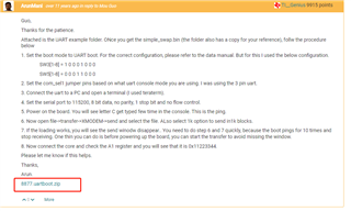
We are trying to do a UART mode boot of a C6657 on a custom PCB.
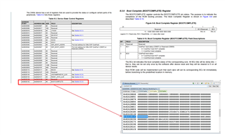
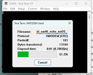
I have looked up articles related to UART BOOT on TI's forum, but when I trying to convert the. out compiled by CCS to XMODEM (supported by C6657 UART BOOT MODE) according to some articles. However, the converted file was downloaded to the device through TeraTerm, the result was that the device always no responding.
So I would like to consult TI engineers on the following questions:
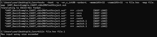
1. How can I convert the. out file generated by CCS compilation into a CRC XMODEM image file supported by UART BOOT MODE?
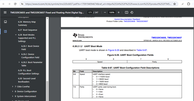
2. During the power on process of the development board, besides configuring the boot mode to UART BOOT MODE( up needed pin voltage), are there any other operations involved?
3. Is there any way I can check my custom PCB really in UART BOOT MODE, (Just can I use CCS with JTAG to check some register value)?