


Other Parts Discussed in Thread: TDA4VH
Hi TI Experts,
Customer is working on TDA4VH SDK9.1.
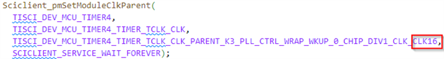
We want to use MCU_TIMER4 to create a 64-Bit timer on R5F MCU-Domain. As cascaded timers did not work (same problem as described in https://e2e.ti.com/support/processors-group/processors/f/processors-forum/1030321/tda4vm-error-count-when-timer7-cascaded-to-timer6 and https://e2e.ti.com/support/processors-group/processors/f/processors-forum/1257454/tda4vm-problem-when-trying-to-put-two-timers-in-cascade-in-main-and-mcu-domains/4847783?tisearch=e2e-sitesearch&keymatch=cascade%20timer#4847783), we detect the overflows by ourselves to generate that 64 bit timer. We want to configure it to run with 250 MHz. As SYSCLK should be 1000MHz we use the following clock source, taken from j784s4_public_combined_TRM_registers.xlsx to set it to 250 MHz:


We select the clock source in code like this:
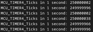
When the timer is enabled counter ticks increment 250000000 in 1 second (we used Osal_delay(1000) to sleep 1 second between reading the ticks). Everything seems to work as expected. See following screenshot:
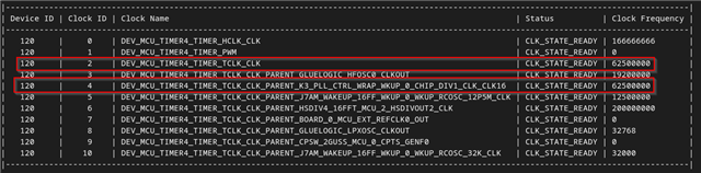
However k3conf tool says, that MCU_TIMER4 is running with 62.5 MHz. Also the variable name indicates, that SYSCLK is divided by 16. There seem to be inconsistencies between implemented code and documentation of the registers described in j784s4_public_combined_TRM_registers.xlsx.
Our questions:
Is our configuration of the timer correct if the counter should be incremented at a rate of 250 MHz? (a practical test seems to suggest that it is correct)
If our configuration is correct, then why is the output of k3conf seemingly wrong?
Kind Regards,
Kevin


