Other Parts Discussed in Thread: AM6442
On the Quick Start Guide (ti.com) and comparing content with ug spruiy9b.pdf
The FR4 is red on the B rev. the first photo on the quick start guide should be replaced by the photo from spruiy9b, page 6 figure 4-1 w/o many of the callouts.
Label the USB type micro-B cable end on the upper left hand side of the fig 4-1 reused. Tell whether it is J11 or J12 used in "Establishing a Serial Connection with the SK"
Please label the Type C (power delivery) connector J8 next to the wall wart connection.
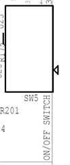
A better picture to replace the DIP switches is attached (red FR4 again)

Disclose the bottom side red(?) LED LD15 is on when power is applied via the USB type C connector.
Does SW5 need to be toggled before/after the USB Type C power applied?