This thread has been locked.

If you have a related question, please click the "Ask a related question" button in the top right corner. The newly created question will be automatically linked to this question.

SK-AM62: How does TCA6424 IO Expander works

Part Number: SK-AM62
Other Parts Discussed in Thread: TCA6424,

Tool/software:

Hi, Dear Expert

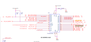
The goal of this thread is try to let "uart1" of M.2 slots real inter-connect to AM62x uart1 (A18/B19/E19/A20)

So we need try to study how does TCA6424 IO Expander work?

Expander code as below.


What's mean for this DTS? show as below

		gpios = <&exp1 11 GPIO_ACTIVE_HIGH>;
		enable-active-high;

Does it mean "UART1_FET_BUF_EN" P12 of TCA6424 set high level?

Need your explanations.

Many Thanks

Gibbs 

  • Hi Gibbs,

            gpios = <&exp1 11 GPIO_ACTIVE_HIGH>;
            enable-active-high;

    I am not sure where this code comes from. I don't see this in the SDK kernel source code. But anyway, please see the kernel device tree binding documentation (<kernel>/Documentation/devicetree/bindings/regulator/fixed-regulator.yaml) for the explanation of "enable-active-high":

      enable-active-high:
        description:
          Polarity of GPIO is Active high. If this property is missing,
          the default assumed is Active low.
        type: boolean

  • Hi, Bin

    This code code come from CC33xx driver patch for AM62EVB

    https://www.ti.com/product/zh-tw/CC3300#software-development

    I believe should be "exp1" TCAN6424, and I wants to know how does it (IO expender) work.

    diff --git arch/arm64/boot/dts/ti/k3-am625-sk.dts arch/arm64/boot/dts/ti/k3-am625-sk.dts
    index 83525949aafd..4f97fad818fc 100644
    --- arch/arm64/boot/dts/ti/k3-am625-sk.dts
    +++ arch/arm64/boot/dts/ti/k3-am625-sk.dts
    @@ -13,6 +13,10 @@ / {
     	compatible = "ti,am625-sk", "ti,am625";
     	model = "Texas Instruments AM625 SK";
     
    +	aliases {
    +		serial3 = &main_uart1;
    +	};
    +
     	opp-table {
     		/* Add 1.4GHz OPP for am625-sk board. Requires VDD_CORE to be at 0.85V */
     		opp-1400000000 {
    @@ -105,7 +109,8 @@ wlan_lten: regulator-6 {
     		regulator-min-microvolt = <3300000>;
     		regulator-max-microvolt = <3300000>;
     		vin-supply = <&vcc_3v3_sys>;
    -		gpios = <&exp1 11 GPIO_ACTIVE_LOW>;
    +		gpios = <&exp1 11 GPIO_ACTIVE_HIGH>;
    +		enable-active-high;
     	};
     
     	wlan_en: regulator-7 {
    @@ -130,6 +135,15 @@ vdd_core: regulator-8 {
     		regulator-always-on;
     		regulator-boot-on;
     	};
    +
    +	uart_buf_en: regulator-9 {
    +		compatible = "regulator-fixed";
    +		regulator-name = "uart_buf_en";
    +		regulator-min-microvolt = <1800000>;
    +		regulator-max-microvolt = <1800000>;
    +		gpios = <&exp1 10 GPIO_ACTIVE_LOW>;
    +		regulator-always-on;
    +	};
     };
     
     &main_pmx0 {
    @@ -201,6 +215,27 @@ main_wlirq_pins_default: main-wlirq-pins-default {
     			AM62X_IOPAD(0x128, PIN_INPUT, 7) /* (B23) MMC2_SDWP.GPIO0_72 */
     		>;
     	};
    +
    +	main_uart1_pins_default: main-uart1-pins-default {
    +		pinctrl-single,pins = < 
    +			AM62X_IOPAD(0x1ac, PIN_INPUT, 2) /* (E19) MCASP0_AFSR.UART1_RXD */
    +			AM62X_IOPAD(0x198, PIN_OUTPUT, 2) /* (A19) MCASP0_AXR2.UART1_RTSn */
    +			AM62X_IOPAD(0x194, PIN_INPUT, 2) /* (B19) MCASP0_AXR3.UART1_CTSn */
    +			AM62X_IOPAD(0x1b0, PIN_OUTPUT, 2) /* (A20) MCASP0_ACLKR.UART1_TXD */
    +		>;
    +	};
    +};
    +
    +&main_uart1 {
    +	status = "okay";
    +	pinctrl-names = "default";
    +	pinctrl-0 = <&main_uart1_pins_default>;
    +
    +	bluetooth {
    +		compatible = "ti,cc33xx-bt";
    +		cc33xx-supply = <&wlan_en>;
    +		max-speed = <115200>;
    +	};
     };
     
     &main_i2c1 {
    @@ -254,12 +289,12 @@ &sdhci2 {
     	#address-cells = <1>;
     	#size-cells = <0>;
     	wlcore: wlcore@2 {
    -		compatible = "ti,wl1837";
    +		compatible = "ti,cc33xx";
     		reg = <2>;
     		pinctrl-names = "default";
     		pinctrl-0 = <&main_wlirq_pins_default>;
     		interrupt-parent = <&main_gpio0>;
    -		interrupts = <72 IRQ_TYPE_EDGE_RISING>;
    +		interrupts = <72 IRQ_TYPE_EDGE_FALLING>;
     	};
     };
    

    I think this is one of key to enable uart1 enable.

            gpios = <&exp1 11 GPIO_ACTIVE_HIGH>;
            enable-active-high;

    Many Thanks

    Gibbs

  • Hi Gibbs,

    I am routing your query to the CC33xx device team for comments.

  • Hello Gibbs,

    "gpios = <&exp1 11 GPIO_ACTIVE_HIGH>" points to WL_LT_EN. It enables the TXS104 on the SK-Am62B-P1 board. This level translator is needed so that the "SOC_WLAN_EN_1V8" pin can be sent to the M.2 connector. Without it, the M.2 connector will not have access to WLAN_ENABLE pin. 

  • To enable UART, add this regulator, which configures the UART1_FET_BUF_EN to be forced low:

    +
    +	uart_buf_en: regulator-9 {
    +		compatible = "regulator-fixed";
    +		regulator-name = "uart_buf_en";
    +		regulator-min-microvolt = <1800000>;
    +		regulator-max-microvolt = <1800000>;
    +		gpios = <&exp1 10 GPIO_ACTIVE_LOW>;
    +		regulator-always-on;
    +	};

    This patch is included in SDK 1.0.0.3: https://www.ti.com/tool/download/CC33XX-LINUX-MPU