This thread has been locked.
If you have a related question, please click the "Ask a related question" button in the top right corner. The newly created question will be automatically linked to this question.
Tool/software:
Hi Support Team,
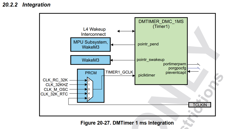
I have been asked about the DMTimer 1ms by a customer who uses the AM3352.
We are currently developing a model that uses this timer and interrupts at 1msec intervals,
but for some reason, this interrupt may not be triggered.
Counter Register (TCRR) itself is counting up normally,
but when it goes OverFlow and reaches the value in the Load Register (TLDR),
the OVF_IT_FLAG bit in the Status Register (TISR) does not hit, and the interrupt is not triggered.
This state is called "no interrupts".
Also, in this state, TOCR is counting up.
TRM: 20.2.3.1.1.1 1 ms Tick Generation describes the following,
but I cannot find a description of what triggers the filtering.
> The Timer Overflow Counter Register (TOCR) and the Timer Overflow Wrapping Register (TOWR) are used for interrupt filtering.
The following description is given in the NOTE section, which also recognizes that the 5 registers
are used in their default state (all 0s), so the function of this correction is turned off.
> By default, the TPIR, TNIR, TCVR, TOCR, TOWR registers and the associated logic are in reset mode (all 0s)
and have no action on the programming model of the DMtimer_dmc1ms.
Could you please tell me what triggers the interrupts to be filtered?
Please contact me if you have any clarification or information needed.
Best Regards,
Kanae
Hello Kanae,
How are you programming the DM Timer? e.g., are you using a driver from a particular operating system?
I am sending your thread to a member of our hardware team for now - I'm the Linux guy, but I'm on vacation until July 15.
Regards,
Nick
Hi Nick,
Thank you for your reply.
Here are the details of issue form the customer.
S/W info:
-> We are not using Linux or other operating systems, but are running on bare metal.
Some interrupt handlers (exceptionhandler.S) are used in AM335X_StarterWare_02_00_01_01
Occurrence rate of issue:
-> The rate of occurrence is indeterminate. It may not occur for several weeks,
or it may occur at intervals of about one hour in rapid succession.
We are trying to increase the rate of occurrence by changing various conditions,
but have not found any triggers at present.
Situation in which this issue occurs:
-> In most cases, the issue occurs during tests of prototype boards.
Specific use case of the function:
-> Interrupt is enabled as soon as the system starts, and is always enabled until the power is turned off.
For initialization,
IRQENABLE_SET = (1 << 1); // set OVF
// CLK_M_OSC (24MHz), so set 1msec as follows
TCRR = (0xffffffffff - (24 * 1000 - 1));
TLDR = (0xffffffffff - (24 * 1000 - 1));
TCLR = (1 << 1); // 1 = auto_rel : Set as set in Auto-reload mode overflow, when interrupt occurs,
IRQSTATUS = (1 << 1); // Clear OVF.
If you need any other information, please let me know.
Best Regards,
Kanae
Hello Kanae,
Thank you.
I am reviewing the inputs.
Please refer below note
Regards,
Sreenivasa
Kanae, can you give more details on the missing interrupt?
-What is the IdleMode and AutoIdle set to in TIOCP_CFG?
-how is the previous interrupt cleared?
-when an interrupt is missed, what is the action? You said it could happen once every hour, but how do you reset the IP
-what is the difference between the proto boards and the other boards?
-do they use a crystal for the 24MHz input? Can they test with LVCMOS square clock input? This will help eliminate any noise related issues.
-what else in their system is running? What other peripherals are in use? Can they pinpoint what the application was doing when the interrupt was missed?
Regards,
James
Hi James,
Thank you for your support.
The customer's responses are listed below.
Please provide more information about the test with LVCMOS square clock input.
James said;
-What is the IdleMode and AutoIdle set to in TIOCP_CFG?
-> IdleMode : 0 = fidle, AutoIdle : 0 = clkfree with reset state.
I have tried with IdleMode set to 1 = nidle, but the same problem occurred.
James said;
-how is the previous interrupt cleared?
-> When an interrupt generats,
TISR = (1 << 1);
and OVF_IT_FLAG is cleared.
James said;
-when an interrupt is missed, what is the action?
You said it could happen once every hour, but how do you reset the IP.
-> Currently, there is no action taken.
To investigate the cause, we have added a process to display the value of the register
in case an interrupt does not generate.
James said;
-what is the difference between the proto boards and the other boards?
-> The same problem had occurred on previous prototype boards.
However, the frequency of occurrence was so low that we did not know what was happening.
There is no difference in S/W and H/W between the previous prototype board and this board,
The cause of the problem is unknown, so it is impossible to determine the difference in the rate of occurrence.
James said;
-do they use a crystal for the 24MHz input?
-> Yes, a crystal oscillator is used.
James said;
-Can they test with LVCMOS square clock input?
-> Sorry, this would mean changing the Clock source to one that is generated internally (CLK_RC_32K or CLK_32KHZ).
James said;
-what else in their system is running? What other peripherals are in use?
Can they pinpoint what the application was doing when the interrupt was missed?
-> PWMSS, EDMA, LCDC, UART, McSPI, McASP, and USBC are running during the aging test.
-> Currently, it is difficult to specify, but if we poll TOCR, we may be able to find the location of the problem to some extent.
Best Regards,
Kanae
Hello Kanae,
thank you.
Let me check internally and also review the inputs.
Regards,
Sreenivasa
Hi Sreenivasa,
Thank you for your support.
I have just added the following explanation of the differences from the previous prototype board to my last post.
There is no difference in S/W and H/W between the previous prototype board and this board,
The cause of the problem is unknown, so it is impossible to determine the difference in the rate of occurrence.
Best Regards,
Kanae
Hello Kanae,
Thank you for the additional inputs.
Let me check and update.
Regards,
Sreenivasa
Hi Sreenivasa,
Thank you for your support.
As I need to report back to the customer, please let me know the expected reply schedule.
Best Regards,
Kanae
Hello Kanae,
Thank you for checking.
The dallas team had holidays and taken vacation.
I will follow-up and try to get their inputs in the next couple of days.
Regards,
Sreenivasa
Hi Sreenivasa,
Thank you for your support.
I will share your above information with my customer.
Looking forward to your reply.
Best Regards,
Kanae
Hi Sreenivasa,
Thank you for your support.
Could you please answer the following question first,
as it is not clear to us what James is asking us to test.
James said; -Can they test with LVCMOS square clock input?
-Can they test with LVCMOS square clock input?
-> Sorry, would this mean changing the Clock source to one that is generated internally (CLK_RC_32K or CLK_32KHZ)?
Best Regards,
Kanae
Hello Kanae,
James said; -Can they test with LVCMOS square clock input?
-Can they test with LVCMOS square clock input?
-> Sorry, would this mean changing the Clock source to one that is generated internally (CLK_RC_32K or CLK_32KHZ)?
James was checking if they could use a 24M LVCMOS clock instead of crystal + internal oscillator.
Regards,
Sreenivasa
Hi Sreenivasa,
Thank you for your support.
I will check with my customer if it is possible to use the 24M LVCMOS clock
instead of the crystal + internal oscillator.
Best regards and continued support.
Kanae
Hi Sreenivasa,
Thank you for your support.
I am checking with the customer about a clock,
but is there any progress on this matter on your side?
Please let us know as we need to report back to the customer
when a reply will be available.
Best Regards,
Kanae
Hi Kanae, sorry for the late reply. There are several clock sources for the 1ms timer, as shown below. Which source is your customer using? Can they try switching to a different source to see if they get a change in behavior?
If they are using CLK_32KHz, this is generated from the PLL. Both CLK_32KHz and CLK_M_OSC ultimately originate from the 24MHz crystal. We have seen issues with the timers when noise is injected into the crystal source. So if one of those are the source, I'd like to see an experiment with the crystal replaced by a LVCMOS oscillator, which is more tolerant of noise injection.
If they are using CLK_32K_RTC, this is also coming from a crystal, but typically the noise will not affect such a slow oscillation, much less than it would affect the 24MHz crystal.
Regards,
James
Hi James,
Thank you for your support!
Here are answers from my customer.
James said;
Which source is your customer using?
Can they try switching to a different source to see if they get a change in behavior?
The current clock source setting is 0 : CLK_M_OSC. With this setting,
the problem always occurred after about 12 hours of aging.
We changed the clock source setting to 1 : CLK_32KHz and
aged the device for 72 hours, but the problem did not occur even once.
(We have not tried 4 : CLK_32K_RTC yet.)
James said;
So if one of those are the source, I'd like to see an experiment with the crystal replaced
by a LVCMOS oscillator, which is more tolerant of noise injection.
We are considering testing by replacing the crystal with an LVCMOS oscillator.
We will report back to you when we have the results.
My customer has a question about your comment below.
James said;
We have seen issues with the timers when noise is injected into the crystal source.
Could you please tell us what kind of issues you are experiencing?
Is it possible that this could cause the problem of interrupts not being triggered?
Best Regards,
Kanae
Hi James,
Thank you for your support.
Could you please tell us what kind of issues you are experiencing?
Is it possible that this could cause the problem of interrupts not being triggered?
When can I get an answer to the above question?
Please let us know as we need to report back to the customer.
Best Regards,
Kanae
Hi Sreenivasa,
Can you please get a response from James on this question?
Please let us know the state of progress.
Best Regards,
Kanae
Hi Kanae,
yes this could be the issue. Noise on the crystal can cause a number of issues, since the crystal is the input to all of the PLLs in the device. We have seen timer values changing backwards and other strange behavior.
The fact that you get better behavior with the CLK_32KHz can be an indication that the issue is noise injection on the 24MHz crystal. The experiment of replacing it with an LVCMOS oscillator will also help further prove that hypothesis.
Regards,
James