

Other Parts Discussed in Thread: AM3358, AM3354, AM3359, , AM3356, SYSCONFIG
Tool/software:
Hi TI Experts,
Can you provide a List of E2Es that can be referred when starting a custom board hardware design?

Hi Board designers,
The below links are a quick reference to the E2Es and FAQs that can be referred when starting a custom design.
E2E
AM335x - Frequency Speed Grade Identification via Register
https://e2e.ti.com/support/processors-group/processors/f/processors-forum/253383/am335x---frequency-speed-grade-identification-via-register/888534?tisearch=e2e-sitesearch&keymatch=zce%25252520zcz#888534
AM3358: are ZCZ ZCE wafers identical?
https://e2e.ti.com/support/processors-group/processors/f/processors-forum/974406/am3358-are-zcz-zce-wafers-identical
AM3358: Temperature grade identification
https://e2e.ti.com/support/processors-group/processors/f/processors-forum/710934/am3358-temperature-grade-identification
AM3354: Device differences vs AM3358
https://e2e.ti.com/support/processors-group/processors/f/processors-forum/1234194/am3354-device-differences-vs-am3358
AM3359 - ZCE, ZCZ differences
https://e2e.ti.com/support/processors-group/processors/f/processors-forum/306246/am3359/1065929?tisearch=e2e-sitesearch&keymatch=zce%252520zcz#1065929
am335x power sequence
https://e2e.ti.com/support/processors-group/processors/f/processors-forum/375367/am335x-power-sequence/1321777?tisearch=e2e-sitesearch&keymatch=zce%25252520zcz#1321777
How much pressure of heat sink can AM3352 chip stand?
https://e2e.ti.com/support/processors-group/processors/f/processors-forum/262665/how-much-pressure-of-heat-sink-can-am3352-chip-stand/919075?tisearch=e2e-sitesearch&keymatch=zce%252525252520zcz#919075
Minimum Number of Layers for AM335x
https://e2e.ti.com/support/processors-group/processors/f/processors-forum/272916/minimum-number-of-layers-for-am335x/953363?tisearch=e2e-sitesearch&keymatch=zce%25252525252525252520zcz#953363
Differences with lower pin packages?
https://e2e.ti.com/support/processors-group/processors/f/processors-forum/213631/differences-with-lower-pin-packages/754374?tisearch=e2e-sitesearch&keymatch=zce%25252525252525252520zcz#754374
AM35x RGMII interface IO voltage
https://e2e.ti.com/support/processors-group/processors/f/processors-forum/189053/am35x-rgmii-interface-io-voltage/678415?tisearch=e2e-sitesearch&keymatch=zce%252525252520zcz#678415
AM335x MPU clock ZCZ to ZCE configuration
https://e2e.ti.com/support/processors-group/processors/f/processors-forum/517675/am335x-mpu-clock-zcz-to-zce-configuration
[FAQ] AM3352: Number of assigned MAC addresses
e2e.ti.com/.../faq-am3352-number-of-assigned-mac-addresses
How to get started with AM335X for customize board development?
https://e2e.ti.com/support/processors-group/processors/f/processors-forum/385444/how-to-get-started-with-am335x-for-customize-board-development
FAQs

Hi All,
Additional inputs
Customer is asking if there is a way their firmware can tell if the CPU is AM3352 or AM554D80 or Z100? Like a register to read from?
Please refer to the below register
Data sheet reference:
3 Device Comparison
Table 3-1 lists the features supported across different AM335x devices
DEV_FEATURE register value(5)
TRM reference
https://www.ti.com/lit/ug/spruh73q/spruh73q.pdf
Table 9-26. dev_feature
Register Field Descriptions Bit Field Type Reset Description 31-0 dev_feature_bits R 0h Device-dependent, See Device Feature Comparison table in device data manual.
FYI, the below thread could be reference.
(+) [Answered] Predefined Macro for AM335x - Processors forum - Processors - TI E2E support forums
Please refer below summary of inputs i received from the expert and this is in line with the above inputs i provided.
The device_id register will be the same for each device of the same silicon revision. You will not be able to determine a specific GPN using this register, just the device revision
The DEV_FEATURE register is the correct register for GPN identification The Device Feature Comparison table in the datasheet has a register value associated with each GPN.
In addition, the efuse_sma register contains details on the package type and max frequency.
Regards,
Sreenivasa
Hi Board designers,
E2Es related to MMC
AM3356: Is a pull-up needed on MMCx_CLK ?
e2e.ti.com/.../am3356-is-a-pull-up-needed-on-mmcx_clk
You need to be more specific with which MMCx_CLK signal function is being used and which pin is it multiplexed? However, I can give you a high-level overview of why an external pull-up may be required.
Each MMCx_CLK signal function is pin multiplexed with other signal functions, where the pins associated with these signal functions default to a GPIO signal function in high-impedance state with a weak internal pull-up or pull-down turned on. An external pull-up is needed to hold the input of the attached device in a valid high logic state until software configures the pin mux logic to source the respective MMC clock signal to the attached device. Internal weak pull-ups are not recommended to hold signals in a valid logic state when not driven. The internal resistors are primary implemented to hold unconnected pins in a valid logic state when no PCB trace is connected to the pin. It is easy for noise to couple into undriven signal traces and over-drive the internal pull resistors, so we recommend external pulls to hold valid logic states any time a PCB trace is connected to a pin.
regards,
Sreenivasa
Hi Board designers,
Refer below FAQ related to AM335x clock:
OSC0 input is powered from the VDDS_OSC power rail, which is 1.8V. Absolute maximum input voltage for this input is VDDS_OSC +0.3V. Absolute minimum is -0.5V. It's important to note that no external voltage should be applied to OSC0 pin before the VDDS_OSC supply has fully ramped-up and stabilized. This means that you should either use an external oscillator powered from VDDS_OSC, or place an external 1.8V buffer powered from VDDS_OSC.
(19) AM3358-EP: Overdriving oscillator input - Processors forum - Processors - TI E2E support forums
(19) AM3358: OSC0 crystal requirements - Processors forum - Processors - TI E2E support forums
(19) AM3358: Frequency accuracy - Processors forum - Processors - TI E2E support forums
Crystals are defined to have an initial frequency accuracy at room temperature. They should also provide another parameter that defines frequency deviation due to temperature change relative to room temperature. They typically provide another parameter that defines a frequency change due to aging.
You must combine all three contributors of frequency error to determine the maximum frequency deviation expected across operating conditions for the life of the product.
I have included a couple of links to crystal datasheets that you can use as examples.
ABM11W-25.0000MHZ-8-D1X-T3: https://abracon.com/Resonators/ABM11W.pdf
ABM10W-25.0000MHZ-8-D1X-T3: https://abracon.com/Resonators/ABM10W.pdf
Keep in mind the crystal doesn't dissipate much power, so there is no significant self-heating. The operating temperature of the crystal is typically the same temperature as the PCB board. Therefore, a crystal rated for 85 degrees Celsius may be good enough for most applications.
(19) AM3358: Am3358 - Processors forum - Processors - TI E2E support forums
The RTC logic in AM335x does not play any role in the various low-power sleep states support by AM335x while power remains on. These low-power sleep states are defined by software, where clocks are stopped for some logic functions and clock frequency reduced for other logic functions. You need to research the various modes supported by your operating system.
The Power Estimator Tool is the best way to understand current consumption based on your specific use case.
The RTC drift will be a function of the crystal circuit you connect to the RTC oscillator. In a typical application the RTC is constantly updated by the processor operating system while it has power, which gets its time from a accurate on-line time source. The RTC only needs to keep time while the processor is turned off. The off-time is typically short relative the time it takes for the drift to be a concern. The RTC will be updated by the operating system again after it turns on the PMIC, the processor boots the operating system, and it gets access to an accurate on-line time source.
Based on your questions, you have not read the TRM or researched what is supported by software. I will not be able to talk you through all of these details. You need to research your options.
The crystal shunt capacitance is in parallel with the series combination of C1 and C2. If the crystal requires a load of 18pf to oscillate at the correct frequency, the formula is saying you subtract the crystal shunt capacitance from the load it expects to determine what external capacitive load needs to be added to reach a load of 18pf. In this case it would be 18pF - 5pf = 13pf. Assuming your PCB traces have zero capacitance, the values for C1 and C2 would need to be 26pf. However, there is a good chance your PCB has 2pf to 3pf of capacitance on each signal trace. You would need to subtract that from the calculated value of 26pf and select a value like 24pf for C1 and C2.
The datasheet limits are for the combination of the external capacitor plus your PCB trace capacitance. Therefore, a crystal that requires 18pf of load would not be a good choice for this device.
I'm not sure why the boards you mentioned were designed to use a crystal that requires a load of 18pf. I suspect the TI board was designed before the oscillator limits were defined and the BeagleBone board simply followed the example and used the same crystal. I would not recommend following their example by selecting a crystal that operates outside of the limits defined by the datasheet.
It is not unusual to find the crystal circuit producing a clipped sinusoid waveform on the oscillator XTALIN. The oscillator will produce a reference clock as long as the signal swing on XTALIN exceeds the Vih min and Vil max values defined in the Electrical Characteristics table of the AM335x datasheet. However, the slow changing sinusoid signal can be problematic in a system with lots of electrical noise.
The slow voltage change of a sinusoid signal makes it easier for electrical noise to couple into the crystal circuit and produce a non-monatomic transition just as the signal crosses the input buffer switching threshold. If the noise source induces enough potential, the non-monatomic event my exceed the hysteresis of the input buffer which causes it to produces a glitch on the internal reference clock. Several customers using AM335x have experienced this issue, where the glitch commonly causes a timer operating from the oscillator clock to suddenly jump forward or backwards in time. The glitch effectively over-clocks the timer logic circuits which causes it to do unpredictable things. This glitch has occasionally caused other issues like the PLL suddenly changing its operating frequency.
I agree radiated emissions from a sinusoid signal are much easier to resolve than emissions from a square wave signal. However, radiated noise can be minimized if your system design implements a high-quality power distribution network and all of the your signal paths have controlled impedance paths with minimum loop inductance. Typically if you minimize radiated emissions, the self induced noise may be acceptable for using a sinusoid source for XTALIN. However, some applications place a system in a noisy electrical environment where it would not be wise to use a sinusoid source. If this is the case, you may need to perform noise immunity testing for your product to understand its susceptibility to external noise sources.
The accuracy of the AM335x reference clock source should be based on system level requirements. For example, you may need a 30 PPM reference clock if an AM335x timer is being used to operate something that needs this level of accuracy.
The 50 PPM limit was defined for AM335x because the RMII Ethernet standard requires this accuracy. The other Ethernet standards only require 100 PPM, so you may be able to back-off on this 50 PPM requirement if not using RMII. However, this depends if you have other system function that require an accuracy of 50 PPM. I would not recommend going above 100 PPM as this may begin to effect other peripheral interfaces.
Keep in mind, a crystal has three contributions to accuracy. There is a parameter that defines initial accuracy, another parameter that defines accuracy over operating temperature, and aging parameter that defines how much the resonate frequency changes over time due to aging effects. When selecting a crystal, you must combine all of these to determine frequency accuracy across all operating conditions for the life of the product.
Reliable start-up is also a concern with crystal selection. The max ESR of the crystal is one of the primary concerns. The AM335x oscillator may not have enough gain to reliably start oscillation if the crystal ESR is too low. Many crystal datasheets define a worst case max ESR value for the entire family of crystals rather than a specific max ESR for the crystal being selected. In most cases the higher frequency crystals in the family will have a much lower max ESR value that what is found in the datasheet. Therefore, you may need to contact the crystal manufacture and request a device specific datasheet for the crystal part number you plan to use.
One way to confirm you have start-up margin, is by inserting a resistor in series with the selected crystal and checking for reliable start-up across all operating conditions. I suggest you begin with a resistor value that is about 5x the max ESR of the crystal. If you have start-up issues with this value you can reduce it to 3x. There is not enough gain margin if oscillation will not reliably start with a 3x resistor. You would need to select a crystal with lower ESR if you find it will not reliably start with a 3X series resistor.
(+) AM3358: RTC CLK_32KHz From PLL accuracy - Processors forum - Processors - TI E2E support forums
Using a 1.8V LVCMOS 32.768kHz oscillator should resolve the issue if it is caused by noise coupling into the crystal circuit. They could easily prove this is the case by removing crystal components and modifying a few systems to source the RTC from an external 32.768kHz LVCMOS source.
(+) AM3358: RTC crystal does not work - Processors forum - Processors - TI E2E support forums
The RTC oscillator is disabled by default at reset release time. See section 20.3.5.19 of the AM335x TRM Rev. P.
AM335x has two internal 32.768KHz clock sources.
The first is named CLK_32KHZ. This source originates from a fractional divider sourced from the peripheral PLL. There is no way to route this clock to any of the device pins.
The second is an optional clock named CLK_32K_RTC. This source originates from the 32K crystal oscillator (OSC1) and has the option of being routed to the CLKOUT2 signal which can be multiplexed to the device XDMA_EVENT_INTR1 pin.
Note: OSC1 has been problematic for some products. It may be easy for noise to couple into the crystal circuit and generate glitches on OSC1's clock output as the slow changing crystal signal crosses the threshold of the input buffer.
Please read sections 8.1.4.3.5 and 20.3.3.8 from the AM335X TRM Rev. K to understand how RTC-only mode works. This mode can be entered only by setting the pmic_power_en pin low by ALARM2 event, and wakeup from RTC-only is possible by ALARM event or ext_wakeup pin event.
For this to work PMIC_PWR_EN register bit0 set to 1 to enable external interrupt.
(+) AM3358: MCASP Clock Generation - Processors forum - Processors - TI E2E support forums
(+) AM3358: Custom board bring up issue - Processors forum - Processors - TI E2E support forums
(+) AM3358: Custom board bringup - Processors forum - Processors - TI E2E support forums
As we usually use oscillators with 40:60 waveform symmetry I have been asked to determine if this is a general requirement (to allow correct operation of the PLLs for example) or driven by any specific interface on the device.
This is a timing constraint that is applied during the design of the processor. It defines the timing assumptions used for timing closure. Exceeding this input specification invalidates the timing closure.
Can you ask the customer to provide the electrical parameters of the crystal and schematic of the crystal circuit they plan to use?
The data sheet defines a maximum ESR value of 48 ohms for a 24MHz crystal. This is approximately 1/3 of 144 ohms which is the worst case negative resistance of the oscillator and about 1/5 of 240 ohms which is the nominal negative resistance of the oscillator. This assume a Rd value of zero ohms.
Our recommended crystal circuit shows an optional series damping resistor (Rd) inserted between the oscillator output and the resonant crystal circuit. This damping resistor is used to reduce drive level of the feedback signal that maintains oscillation which will reduce power dissipation of the crystal.
The data sheet provides a formula for calculating crystal power dissipation. This formula assumes the damping resistor (Rd) value is zero ohms. If the customer determines the power dissipation of the crystal is too high using this formula, they may need to increase the value of Rd. Once they increase the value of Rd, they need to measure voltage across the crystal and replace VDDS_OSC in the power dissipation formula with the measured voltage to determine power dissipation of the crystal. They may need to adjust the value of Rd and repeat the measurement until the optimum value of Rd that maintains safe power dissipation in the crystal has been determined.
Once they have determined the correct value of Rd that is required to maintain safe power dissipation in the crystal, the gain margin required for the oscillator to start can be determined by temporarily inserting a resistor in series with the crystal. The value of this resistor can be increased from zero ohms while operating the product across all expected environmental conditions until the oscillator will no longer start oscillating. The ratio of this resistor value plus the ESR of the crystal divided by the ESR of the crystal represents the gain margin of the oscillator with damping resistor Rd installed.
This crystal has a maximum ESR greater then the vlaue recommended in the data sheet, so they will need to perform the tests described in my previous reply to confirm this crystal allows the system to have enough gain margin for their product.
(+) AM335x and DDR3 termination - Processors forum - Processors - TI E2E support forums
AM3352: Risk for pull up resistor on DDR3 reset signal
I need TI hardware team to tell me if there is a risk of adding a 10K Ω pull-up resistor to the reset pin of the AM3352 DDR3 chip, and if it may cause the device to fail to power on? I added a pull-up resistor to this signal in my design, but ISSI FAE requested to remove this resistor and add a 4.7K Ω pull-down resistor.
I would like to know if there are any risks associated with my design, such as the possibility of DDR initialization failure or inability to boot up?
Yes, technically there should be a pull down to keep the reset signal low during power ramp. In practice, i have never seen an issue during power up, because eventually, the DDR controller will drive the RESET signal low to generate the proper power up sequence that the memory expects. This will be part of the initialization sequence performed by the DDR driver.
Regards,
Sreenivaa
Hi Board designers,
Refer below expert inputs regarding MMC1 and MMC2 configuration.
On the AM335x for the MMC1 and MMC2 there are a multiple pins for the same function.
Customer is checking if they could configure MMC1 for 3.3V and MMC2 for 1.8V
Checking if the pinmux tool supports configuring IOSTEs for MMC1 and MMC2 that would support 3.3V for MMC1 and 1.8V for MMC2.
The data below is for an 8-bit interface for each MMC, using a ZCZ package.
MMC1
VDDSHV1 must be set to 3.3v. this will enable a solution on IOSET_1
MMC2
VDDSHV2 must be set to 1.8v. This will enable IOSET_2
If the IO voltage rails are set as noted above, then the tool will provide the correct solution.
Note that if SDCD and/or SDWP are required, then
MMC1 has SDCD available on VDDSHV3 and VDDSHV6
MMC1 has SDWP available on VDDSHV6
MMC2 has SDCD available on VDDSHV3 and VDDSHV6
MMC2 has SDWP available on VDDSHV6
If required, the IO power rails for the WP and CD signals must be set to match the voltage of the primary interface pins, otherwise a voltage conflict warning will be observed.
Note: There may be other solutions for 4-bit mode
https://e2e.ti.com/cfs-file/__key/communityserver-discussions-components-files/791/mmc_5F00_example.syscfgIn the tool , set the IO voltage rail to the voltage required for the MMC CLK pin (see datasheet for which voltage rails are available for the MMC CLK signal). Do this for both interfaces.
Then add a MMC0, set the “preferred voltage”, set the “use peripheral”. The tool should find a solution assuming the pins meeting the requirement are available. Do this for the second instance.
I attached a sysconfig file as an example.
Regards,
Sreenivasa
Hi Board designers,
Inputs regarding series resistor for processor clock output
The non-monotonic distortion on the looped back clock pin will result in a clock glitch inside the device if the non-monotonic distortion over-laps the input buffer’s switching threshold and the amplitude of this distortion is greater than the input buffer’s hysteresis. The synchronous logic circuits in the SPI module can be over-clocked if the duration of the glitch is short. Unpredictable behavior will occur if portions of the logic see the clock transition while other portion of the logic do not see the clock transition.
The customer’s attempt to increased distortion also appears to be increasing the duration of the distortion. This is most likely creating a longer glitch that allows all of the logic to see the clock transition.
The best solution is to place a series 22 – 33 ohm resistor as close as possible to the AM335x pin (less than 200mils). This shifts the non-monotonic step to a high voltage on rising edges and a lower voltage on falling edges, which shifts the distortion away from the input buffer’s switching threshold.
Regards,
Sreenivasa
Hi Board designers,
Refer below FAQ for useful information related to
Device Portals:
Other:
Regards,
Sreenivasa
Hi Board Designers,
VDD_MPU_MON Connections
This pin was meant to provide feedback to the PMIC so the point of regulation is closer to the processor. In this case it is returned from on-die connections.
The feedback was never expected to compensate for high frequency power demands sourced by local decoupling capacitors. This pin was provided as a way to minimize dc voltage drop across power traces of the PCB and device package.
This may become more important if decide to support higher speed grades in the future.
We recommend connecting this pin to the VDD_MPU power source if it is not going to used as a Kelvin connection to the PMIC or leave it open.
This terminal provides a dedicated Kelvin connection to the VDD_MPU power rail on the AM335x device. When it is not used to provide feedback to a voltage regulator circuit it can be used as another VDD_MPU power terminal.
VDD_MPU_MON is not meant to carry current; it is simply a Kelvin connection to VDD_MPU to monitor the voltage inside of the SoC. Because of inductance introduced in signal paths, we find most PMIC applications are better suited without it (leave it floating).

This pin is used if you want to provide feedback to the PMIC directly from the AM335X VDD_MPU internal plane. This would negate voltage drops over the external VDD_MPU rail. If a good solid VDD_MPU power plane is designed on the PCB this connection is usually not necessary and VDD_MPU_MON can be directly tied to VDD_MPU.
Before using the AM335x VDD_MON terminal, you need to confirm the power supply being used allows a remote sense that originates at the load. Many power sources are only stable when the feedback path is located near the power supply output. These power supplies may not provide a stable ouptut when using a remote sense like the one provided by the AM335x VDD_MON terminal.
What is you opinion on using the VDD_MPU_MON output from the am335x to the TPS65217C pmic feedback pin to help compensate? Will the PMIC be able to remain stable?
The VDD_MPU_MON terminal was added as a way to provide a remote feedback to the power source. However, we found the PMIC output was not stable when VDD_MPU_MON was connected to the PMIC feedback input. This instability occurs because the PMICs were designed with an expectation that the feedback input would be connected directly to their output capacitor.
What is the intended usage of VDD_MPU_MON? Is this intended to be a galvanic sense pin to feed back to the PMIC?
The answer to the question is, yes.
This terminal is an isolated connected to the VDD_MPU domain on the silicon. The plan is to connect this terminal to the PMIC feedback input so any voltage drop on the VDD_MPU signal path can be compensated by the power supply.
AM335x: VDD_MPU_MON left floating
Not connecting the VDD_MPU_MON terminal to a power source is equivalent to not connecting one of the VDD_MPU power terminals.
this signal does not have a low enough impedance inside the AM335x device to be useful power source. Therefore, system performance is not compromised by not connecting the VDD_MPU_MON terminal to the VDD_MPU power source.
We recommend this terminal be connected as shown in the AM335x data sheet.
AM3358: impedance value between VCC_CORE and GND
You need to be careful using a multimeter to measure impedance of a semiconductor pin. Some multimeters may source a potential that is greater than the recommended operating condition of the pin being measured. If so, there is a chance the measurement could create an Electrical Over Stress (EOS) condition for the pin and damage the device.
There is another concern. If the multimeter sources enough current to power a pin, this is likely a violation of the device power sequence requirements.
Regards,
Sreenivasa
Hi Board Designers,
FYI
we are looking for a mean to identify the temp grade of an AM3358 populated on a board, we did find from the datasheet that the Device Identification inside the CPU might be of help, but we are lacking details to see if the actual temp grade of the chip is part of it or not, and if so, how do we access it
This information is not coded in the device.
This was not possible on PG 1.0 devices, but we will have an EFUSE_SMA register on 2.x devices (at offset 0x7FC).
Using bits 12:0 of that register, one can determine the speed capability of the device. Note that the values differ by package type (ZCZ vs. ZCE).
| Max Spd | 300MHz | 600MHz | 720MHz | 800MHz | 1GHz |
| ZCZ | x1FEF | x1FAF | x1F2F | x1E2F | x1C2F |
| ZCE | x1FDF | x1F9F | N/A | N/A |
N/A |
(+) AM3352:Difference temp grade - Processors forum - Processors - TI E2E support forums
Is the temperature grade only difference between AM3352BZCZD80 and AM3352BZCZA80?
When I check the "Quality, reliability & packaging data" for each device, they seem to be exactly the same,
is it correct that the process for each device is the same and the test conditions are just different?
Correct, the only difference ion these part numbers is the temperature grade. Full details are in the Device Nomenclature section of the datasheet,
I don't have all the details, but I believe the process/testing is the same for the devices with the results determining the grade.
Regards,
Sreenivasa
Hi Board Designers,
FYI,
(+) AM3352: HS part number - Processors forum - Processors - TI E2E support forums
Are the following part numbers HS devices?
AM3352BZCZ80
AM3352BZCZD80
1. Please provide the HS part number. I will ask the sales for a quote.
2. Can I get a sample?
3. Are there any purchase restrictions (NDA, quantity, specific customers, specific industries, etc.)
As noted in the referenced e2e,
"There's special customer engagement required for AM335x HS as the customer key set needs to be programmed at TI fab.
This is AM35x security resource download portal access request link.
https://www.ti.com/drr/opn/AM335X-RESTRICTED-SW"
The HS device has a special customer P/N.
Please work with TI local team to get more details on AM335x HS customer engagement process.
Regards,
Sreenivasa
Hi Board Designers,
FYI, related to USB interface:
PROCESSOR-SDK-RTOS-AM335X Software development kit (SDK) | TI.com
(+) AM3352: AM3352 USB Eye Diagram Pattern - Processors forum - Processors - TI E2E support forums
AM3352 USB Eye Diagram Pattern
For device mode, USB_ID pin needs to be left floating. The above schematic capture does not reflect this. Please confirm USB_ID state in your system.
Once this is done and assuming you are using Linux, the 'modprobe g_zero' commands needs to be used. Are you able to see the below after entering this command?

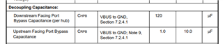
in our reference design, there's a 120uF for USB application. can this 120uF electrolytic capacitor be replaced by ceramic capacitor?
and can this 120uF be divided into several smaller capacitors?
Generally, it should be ok, but please pay attention to the following differences:
1. The value of ceramic capacitor can drop when the applied voltage is higher. Please choose ceramic capacitors with higher voltage rating or leave more margin in capacitance selection.
2. Ceramic caps usually have relatively smaller ESR. When several smaller caps in parallel the ESR can be even smaller. The dumping performance can be influences so please check whether it's necessary to add small resistors in the loop.
3. Thermal performance can be different, please check the application condition and datasheets.
4. The price can be different.
ou need to add the 120uF cap, you can refer to the below document.
M335x USB ID pin is controlled like follows.

USBn_ID has voltage applied by 120kΩ Pull Up. Does this circuit damage AM335x?
AM335x didn't change to USB Host even they pulled off the 120kΩ Pull Up.
Yes, this circuit will certainly damage the AM335x device. Please see bullet #1 in the schematic review checklist.
processors.wiki.ti.com/.../AM335x_Schematic_Checklist
another question is if we don't use the FAULT function, can this pin left float? I see it's an OD structure.
Yes, I think you can leave it float if you are not using it, since it's active-low open-drain output.
Regards,
Sreenivasa
FYI, AM3352: Automotive qualification
The automotive variant of AM335x is DRA60x/DRA61x Jacinto5 Entry device. This is Automotive Qualified Device (AEC-100). This device datasheet is under NDA, and you should contact your local TI representative to get it. The TRM and silicon errata are common with AM335x device.
Regards,
Sreenivasa