This thread has been locked.

If you have a related question, please click the "Ask a related question" button in the top right corner. The newly created question will be automatically linked to this question.

AM623: Custom board, u-boot device tree changes for ethernet does not take effect

Part Number: AM623
Other Parts Discussed in Thread: SK-AM62B-P1

Tool/software:

Hello,

Our custom board uses another design than the EVM, its another phy and the clock is obtained from the SOC (MCU_SPI0_CS1.MCU_OBSCLK0). So I need to change the U-Boot device tree to get the ethernet up.

I use the same dts as for the AM62 lp sk EVM, but added the modifications to network in the k3-am62x-sk-common.dtsi. The k3-am62-lp-sk.dtb is compiled ok, but my changes does not take effect when the u-boot.img runs (using dfu load). 

I have:

CONFIG_DEFAULT_DEVICE_TREE="k3-am62-lp-sk"

But the mkimage -l u-boot.img lists this dtb: Image 1 (fdt-0) Description: k3-am625-sk

It looks wrong to me.. as I would expect k3-am62-lp-sk.

I tried many changes but keeps getting the same error during u-boot.img, and there is no sign that my changes are loaded. I get:

Net:   Could not get PHY for ethernet@8000000port@1: addr 0
am65_cpsw_nuss_port ethernet@8000000port@1: phy_connect() failed
No ethernet found.

So where do I make the changes in order to have the phy working?

Any help is appreciated!

Thanks

Lars

  • I use this defconfig:
    UBOOT_MACHINE = "am62x_lpsk_a53_defconfig"

    These are my changes to k3-am62x-sk-common.dtsi to support the dual Marvell PHY ethernet ports, and clock setup (as on beagleplay):

    @@ -5,11 +5,10 @@
      * Copyright (C) 2021-2023 Texas Instruments Incorporated - https://www.ti.com/
      */
     
     #include <dt-bindings/leds/common.h>
     #include <dt-bindings/gpio/gpio.h>
    -#include <dt-bindings/net/ti-dp83867.h>
     #include "k3-am625.dtsi"
     
     / {
     	aliases {
     		serial2 = &main_uart0;
    @@ -204,10 +203,27 @@
     			AM62X_IOPAD(0x130, PIN_OUTPUT, 0) /* (AE19/W16) RGMII1_TXC */
     			AM62X_IOPAD(0x12c, PIN_OUTPUT, 0) /* (AD19/V15) RGMII1_TX_CTL */
     		>;
     	};
     
    +	main_rgmii2_pins_default: main-rgmii2-default-pins {
    +		pinctrl-single,pins = <
    +			AM62X_IOPAD(0x0184, PIN_INPUT, 0) /* (AE23) RGMII2_RD0 */
    +			AM62X_IOPAD(0x0188, PIN_INPUT, 0) /* (AB20) RGMII2_RD1 */
    +			AM62X_IOPAD(0x018c, PIN_INPUT, 0) /* (AC21) RGMII2_RD2 */
    +			AM62X_IOPAD(0x0190, PIN_INPUT, 0) /* (AE22) RGMII2_RD3 */
    +			AM62X_IOPAD(0x0180, PIN_INPUT, 0) /* (AD23) RGMII2_RXC */
    +			AM62X_IOPAD(0x017c, PIN_INPUT, 0) /* (AD22) RGMII2_RX_CTL */
    +			AM62X_IOPAD(0x016c, PIN_OUTPUT, 0) /* (Y18) RGMII2_TD0 */
    +			AM62X_IOPAD(0x0170, PIN_OUTPUT, 0) /* (AA18) RGMII2_TD1 */
    +			AM62X_IOPAD(0x0174, PIN_OUTPUT, 0) /* (AD21) RGMII2_TD2 */
    +			AM62X_IOPAD(0x0178, PIN_OUTPUT, 0) /* (AC20) RGMII2_TD3 */
    +			AM62X_IOPAD(0x0168, PIN_OUTPUT, 0) /* (AE21) RGMII2_TXC */
    +			AM62X_IOPAD(0x0164, PIN_OUTPUT, 0) /* (AA19) RGMII2_TX_CTL */
    +		>;
    +	};
    +
     	main_usb1_pins_default: main-usb1-pins-default {
     		pinctrl-single,pins = <
     			AM62X_IOPAD(0x0258, PIN_OUTPUT, 0) /* (F18/E16) USB1_DRVVBUS */
     		>;
     	};
    @@ -279,29 +295,55 @@
     	disable-wp;
     };
     
     &cpsw3g {
     	pinctrl-names = "default";
    -	pinctrl-0 = <&main_rgmii1_pins_default>;
    +	pinctrl-0 = <&main_rgmii1_pins_default>, <&main_rgmii2_pins_default>,
    +		<&gbe_pmx_obsclk>;
    +	assigned-clocks = <&k3_clks 157 70>, <&k3_clks 157 20>;
    +	assigned-clock-parents = <&k3_clks 157 72>, <&k3_clks 157 22>;
     };
     
     &cpsw_port1 {
     	phy-mode = "rgmii-rxid";
     	phy-handle = <&cpsw3g_phy0>;
     };
     
    +&cpsw_port2 {
    +	phy-mode = "rgmii-rxid";
    +	phy-handle = <&cpsw3g_phy1>;
    +	status = "enabled";
    +};
    +
     &cpsw3g_mdio {
     	status = "okay";
     	pinctrl-names = "default";
     	pinctrl-0 = <&main_mdio1_pins_default>;
     
     	cpsw3g_phy0: ethernet-phy@0 {
    +		compatible = "marvell,88E1510";
     		reg = <0>;
    -		ti,rx-internal-delay = <DP83867_RGMIIDCTL_2_00_NS>;
    -		ti,fifo-depth = <DP83867_PHYCR_FIFO_DEPTH_4_B_NIB>;
    -		ti,min-output-impedance;
    +		device_type = "ethernet-phy";
    +		/* Set LED0 control: */
    +		/* On - Link, Blink - Activity, Off - No Link */
    +		marvell,reg-init = <3 0x10 0 0x1011>;
    +		max-speed = <100>;
     	};
    +
    +	cpsw3g_phy1: ethernet-phy@1 {
    +		compatible = "marvell,88E1510";
    +		reg = <1>;
    +		device_type = "ethernet-phy";
    +		/* Set LED0 control: */
    +		/* On - Link, Blink - Activity, Off - No Link */
    +		marvell,reg-init = <3 0x10 0 0x1011>;
    +		max-speed = <100>;
    +	};
    +};
    +
    +&cpsw_port2 {
    + bootph-pre-ram;
     };
     
     &mailbox0_cluster0 {
     	mbox_m4_0: mbox-m4-0 {
     		ti,mbox-rx = <0 0 0>;
    @@ -408,10 +450,16 @@
     	mcu_gpio1_pins_default: mcu-gpio1-default-pins {
     		pinctrl-single,pins = <
     			AM62X_MCU_IOPAD(0x003c, PIN_INPUT, 7) /* (D5) MCU_MCAN1_TX.MCU_GPIO0_15 */
     		>;
     	};
    +
    +	gbe_pmx_obsclk: gbe-pmx-clk-default {
    +		pinctrl-single,pins = <
    +			AM62X_MCU_IOPAD(0x0004, PIN_OUTPUT, 1) /* (B8) MCU_SPI0_CS1.MCU_OBSCLK0 */
    +		>;
    +	};
     };
     
     &main_pmx0 {
     	bootph-pre-ram;
     	main_uart1_pins_default: main-uart1-pins-default {


    I also added Marvell phy driver:
    CONFIG_PHY_MARVELL=y

  • Hello, I have assigned the query to the subject-matter expert.
    Please expect response in some time.

    Regards,
    Aparna

  • Update, I find that the yocto build also produces u-image-dtb.img. This image includes the desired dtb. However, when executed, there is still the error and no sign that my dtb changes are included.

    $ mkimage -l u-boot-dtb.img
    FIT description: Firmware image with one or more FDT blobs
    Created: Tue Mar 19 21:31:40 2024
    Image 0 (firmware-1)
    Description: U-Boot 2023.04-ti-gf9b966c67473 for am62x board
    Created: Tue Mar 19 21:31:40 2024
    Type: Firmware
    Compression: uncompressed
    Data Size: 1192552 Bytes = 1164.60 KiB = 1.14 MiB
    Architecture: ARM
    OS: U-Boot
    Load Address: 0x80800000
    Hash algo: crc32
    Hash value: 592d1241
    Image 1 (fdt-1)
    Description: k3-am62-lp-sk
    Created: Tue Mar 19 21:31:40 2024
    Type: Flat Device Tree
    Compression: uncompressed
    Data Size: 59712 Bytes = 58.31 KiB = 0.06 MiB
    Architecture: ARM
    Hash algo: crc32
    Hash value: 27e78e6b
    Default Configuration: 'conf-1'
    Configuration 0 (conf-1)
    Description: k3-am62-lp-sk
    Kernel: unavailable
    Firmware: firmware-1
    FDT: fdt-1
    Loadables: firmware-1

  • Update: with u-image-dtb.img I now get the modified device tree loaded - but the two ethernet devices and phy still fails, the device tree changes still as the patch posted above.

  • Hello Lars,

    A couple initial questions:

    1. What SDK version are you using?

    2. Any particular reason for using the configuration for AM62x LP SK EVM as opposed to the AM62x SK EVM?

    3. To try and isolate specifically what changes might have caused an issue, can you first try using the default SDK U-boot am62x_evm_a53_defconfig and testing with your device tree for the Marvell PHYs (ideally first test just one CPSW port enabled- from my understanding by default only CPSW port 1 is enabled in U-boot).

    -Daolin

  • Hi Daolin,

    1. the SDK used is 9.02, it was used to compile the keywriter for secure boot. Now we use Yocto and the meta-ti layer.

    2. Yes, our board is also using the low power devices.

    3. Correct, initially a single port was there - I added the second one. The current status is, that the customized dtb is compiled and is loaded during boot. But the modified ethernet port config does not work. I took the nodes from the beagleplay dts, as our design is the same. So we have added this pin mux config: gbe_pmx_obsclk which must enable the clock for the phy. However, we cant measure that clock. I guess that causes the "phy_connect() failed" message?

    Thanks,

    Lars

  • Hi Lars,

    Thanks for confirming and the additional explanation. Just for additional clarification, both ethernet ports are failing?

    The current status is, that the customized dtb is compiled and is loaded during boot. But the modified ethernet port config does not work. I took the nodes from the beagleplay dts, as our design is the same. So we have added this pin mux config: gbe_pmx_obsclk which must enable the clock for the phy. However, we cant measure that clock. I guess that causes the "phy_connect() failed" message?

    Not having a PHY clock could potentially be a reason for the "phy_connect() failed" message. The "Could not get PHY for ethernet@8000000port@1: addr 0" is most likely coming from drivers/net/phy/phy.c.

    struct phy_device *phy_connect(struct mii_dev *bus, int addr,
    			       struct udevice *dev,
    			       phy_interface_t interface)
    {
    	struct phy_device *phydev = NULL;
    	uint mask = (addr >= 0) ? (1 << addr) : 0xffffffff;
    
    #ifdef CONFIG_PHY_FIXED
    	phydev = phy_connect_fixed(bus, dev);
    #endif
    
    #ifdef CONFIG_PHY_NCSI
    	if (!phydev && interface == PHY_INTERFACE_MODE_NCSI)
    		phydev = phy_device_create(bus, 0, PHY_NCSI_ID, false);
    #endif
    
    #ifdef CONFIG_PHY_ETHERNET_ID
    	if (!phydev)
    		phydev = phy_connect_phy_id(bus, dev, addr);
    #endif
    
    #ifdef CONFIG_PHY_XILINX_GMII2RGMII
    	if (!phydev)
    		phydev = phy_connect_gmii2rgmii(bus, dev);
    #endif
    
    	if (!phydev)
    		phydev = phy_find_by_mask(bus, mask);
    
    	if (phydev)
    		phy_connect_dev(phydev, dev, interface);
    	else
    		printf("Could not get PHY for %s: addr %d\n", bus->name, addr);
    	return phydev;
    }

    A previous test I've done is enabling the 2nd CPSW port in U-boot on SDK 09.02 for SK-AM62B-P1 EVM and this successfully worked when I changed the contents of "k3-am62x-sk-common-u-boot.dtsi" according to https://e2e.ti.com/support/processors-group/processors/f/processors-forum/1380586/am620-q1-enabling-eth1-in-u-boot-shell

    I need to do some research into how the various dts/dtsi files are selected/built into the U-boot binaries. In the meantime, you can try implementing your changes to "k3-am62x-sk-common-u-boot.dtsi" and see if the result is different. Of course, it may still be an issue with not having a PHY clock.

    One reason why I think it is important to use "k3-am62x-sk-common-u-boot.dtsi" is because there is a workaround for the MDIO driver indicated by the below section in the dtsi file. I do not know if this dtsi file is incorporated into you U-boot build.

    &cpsw3g {
    	reg = <0x0 0x8000000 0x0 0x200000>,
    	      <0x0 0x43000200 0x0 0x8>;
    	reg-names = "cpsw_nuss", "mac_efuse";
    	/delete-property/ ranges;
    	/* This is WA because MDIO driver is not DM enabled */
    	pinctrl-0 = <&main_mdio1_pins_default &main_rgmii1_pins_default>;
    	bootph-pre-ram;
    
    	cpsw-phy-sel@04044 {
    		compatible = "ti,am64-phy-gmii-sel";
    		reg = <0x0 0x00104044 0x0 0x8>;
    		bootph-pre-ram;
    	};
    };

    -Daolin

  • Hello,

    I actually already did that, as I also found that comment.. Here is my k3-am62x-sk-common-u-boot.dtsi:

    &mcu_pmx0 {
    	bootph-pre-ram;
    	gbe_pmx_obsclk: gbe-pmx-clk-default {
    		pinctrl-single,pins = <
    			AM62X_MCU_IOPAD(0x0004, PIN_OUTPUT, 1) /* (B8) MCU_SPI0_CS1.MCU_OBSCLK0 */
    		>;
    	};
    };
    
    &cpsw3g {
    	reg = <0x0 0x8000000 0x0 0x200000>,
    	      <0x0 0x43000200 0x0 0x8>;
    	reg-names = "cpsw_nuss", "mac_efuse";
    	/delete-property/ ranges;
    	/* This is WA because MDIO driver is not DM enabled */
    	pinctrl-0 = <&gbe_pmx_obsclk &main_mdio1_pins_default &main_rgmii1_pins_default &main_rgmii2_pins_default>;
    	bootph-pre-ram;
    
    	cpsw-phy-sel@04044 {
    		compatible = "ti,am64-phy-gmii-sel";
    		reg = <0x0 0x00104044 0x0 0x8>;
    		bootph-pre-ram;
    	};
    };
    
    &cpsw_port1 {
    	phy-mode = "rgmii-rxid";
    	phy-handle = <&cpsw3g_phy0>;
    	bootph-pre-ram;
    };
    
    &cpsw_port2 {
    	phy-mode = "rgmii-rxid";
    	phy-handle = <&cpsw3g_phy1>;
    	bootph-pre-ram;
    };
    
    &cpsw3g_mdio {
    	status = "okay";
    	pinctrl-names = "default";
    
    	cpsw3g_phy0: ethernet-phy@0 {
    		compatible = "marvell,88E1510";
    		reg = <0>;
    		device_type = "ethernet-phy";
    		/* Set LED0 control: */
    		/* On - Link, Blink - Activity, Off - No Link */
    		marvell,reg-init = <3 0x10 0 0x1011>;
    		max-speed = <100>;
    	};
    
    	cpsw3g_phy1: ethernet-phy@1 {
    		compatible = "marvell,88E1510";
    		reg = <1>;
    		device_type = "ethernet-phy";
    		/* Set LED0 control: */
    		/* On - Link, Blink - Activity, Off - No Link */
    		marvell,reg-init = <3 0x10 0 0x1011>;
    		max-speed = <100>;
    	};
    };
    

    Notice, I added the pinmux change for the phy clk, now I get a 25Mhz clock going.

    But it gives the same error after boot up:

    Net: Could not get PHY for ethernet@8000000port@1: addr 0
    am65_cpsw_nuss_port ethernet@8000000port@1: phy_connect() failed
    No ethernet found.

    Thanks

  • Hi Lars,

    I actually already did that, as I also found that comment.. Here is my k3-am62x-sk-common-u-boot.dtsi:
    These are my changes to k3-am62x-sk-common.dtsi to support the dual Marvell PHY ethernet ports, and clock setup (as on beagleplay):

    Thanks for clarifying, I initially thought you only made changes to k3-am62x-sk-common.dtsi according to a previous response. When you made changes to k3-am62x-sk-common-u-boot.dtsi did you revert the changes you made to k3-am62x-sk-common.dtsi? The reason why I ask is because when I made changes to enable the 2nd port, I only changed the k3-am62x-sk-common-u-boot.dtsi and did not modify k3-am62x-sk-common.dtsi.

    1. Other than these two dtsi, did you make any changes to other files?

    2. Can you share your am62x_lpsk_a53_defconfig with any changes you made to enable your Marvell PHY?

    But it gives the same error after boot up:

    3. After this error, are you able to run commands in the U-boot environment? If so, can you run "mii dump 0 0" to check if the register 0 content of the PHY show up?

    => mii 
    mii - MII utility commands
    
    Usage:
    mii device                           - list available devices
    mii device <devname>                 - set current device
    mii info  <addr>                    - display MII PHY info
    mii read  <addr> <reg>              - read MII PHY <addr> register <reg>
    mii write <addr> <reg> <data>       - write MII PHY <addr> register <reg>
    mii modify <addr> <reg> <data> <mask> - modify MII PHY <addr> register <reg>
                                           updating bits identified in <mask>
    mii dump  <addr> <reg>              - pretty-print <addr> <reg> (0-5 only)
    Addr and/or reg may be ranges, e.g. 2-7.
    => mii device
    MII devices: 'mdio@f00' 'ethernet@8000000port@1' 
    Current device: 'mdio@f00'
    => mii device ethernet@8000000port@1
    => mii device
    MII devices: 'mdio@f00' 'ethernet@8000000port@1' 
    Current device: 'ethernet@8000000port@1'
    => mii dump 0 0

    -Daolin

  • Hello Daolin,

    I kept my ethernet changes in common.dtsi as well... can I attach all my dts files and my .config in here, or by mail? Basically only this is added to include the Marvell driver: CONFIG_PHY_MARVELL=y

    When I play around with the mii command in u-boot, it crash u-boot when i try to dump.

    Lars

  • Daolin,

    I believe it has to do with errata: i2329 MDIO: MDIO interface corruption (CPSW and PRU-ICSS), and I am trying the bitbang alternative.
    I now have linux running so I can better troubleshoot using the dmesg log.

    - Lars

  • I tried to configure MDIO using bitbang (as beagleplay does and as described in SDK 8). However, still stuck with:

    [    1.362783] [Firmware Warn]: /mdio/ethernet-phy@0: Whitelisted compatible string. Please remove
    [    1.371738] mdio_bus gpio-0: MDIO device at address 0 is missing.
    [    1.377834] [Firmware Warn]: /mdio/ethernet-phy@1: Whitelisted compatible string. Please remove
    [    1.386727] mdio_bus gpio-0: MDIO device at address 1 is missing.
    

    My dtsi as used in linux, kernel 6.1.82

    // SPDX-License-Identifier: GPL-2.0
    /*
     * Common dtsi for CPB639 and derivatives
     *
     * Copyright (C) 2024 Doms
     */
    
    #include <dt-bindings/leds/common.h>
    #include <dt-bindings/gpio/gpio.h>
    #include "k3-am625.dtsi"
    
    / {
    	aliases {
    		gpio0 = &main_gpio0;
    		gpio1 = &main_gpio1;
    		serial0 = &main_uart2;
    		serial1 = &main_uart1;
    		serial2 = &main_uart0;
    		serial3 = &main_uart3;
    		serial4 = &main_uart4;
    		serial5 = &main_uart5;
    		serial6 = &main_uart6;
    		serial7 = &mcu_uart0;
    		serial8 = &wkup_uart0;
    		mdio-gpio0 = &mdio0;
    		mmc0 = &sdhci0;
    		mmc1 = &sdhci1;
    		ethernet0 = &cpsw_port1;
    		ethernet1 = &cpsw_port2;
    		usb0 = &usb0;
    		usb1 = &usb1;
    	};
    
    	chosen {
    		#address-cells = <2>;
    		#size-cells = <2>;
    		ranges;
    
    		stdout-path = "serial2:115200n8";
    		bootargs = "console=ttyS2,115200n8 earlycon=ns16550a,mmio32,0x02800000";
    	};
    
    	memory@80000000 {
    		device_type = "memory";
    		/* 2G RAM */
    		reg = <0x00000000 0x80000000 0x00000000 0x80000000>;
    
    	};
    
    	reserved-memory {
    		#address-cells = <2>;
    		#size-cells = <2>;
    		ranges;
    
    		ramoops@9c700000 {
    			compatible = "ramoops";
    			reg = <0x00 0x9c700000 0x00 0x00100000>;
    			record-size = <0x8000>;
    			console-size = <0x8000>;
    			ftrace-size = <0x00>;
    			pmsg-size = <0x8000>;
    		};
    
    		/* global cma region */
    		linux,cma {
    			compatible = "shared-dma-pool";
    			reusable;
    			size = <0x00 0x8000000>;
    			linux,cma-default;
    		};
    
    		rtos_ipc_memory_region: ipc-memories@9c800000 {
    			compatible = "shared-dma-pool";
    			reg = <0x00 0x9c800000 0x00 0x00300000>;
    			no-map;
    		};
    
    		mcu_m4fss_dma_memory_region: m4f-dma-memory@9cb00000 {
    			compatible = "shared-dma-pool";
    			reg = <0x00 0x9cb00000 0x00 0x100000>;
    			no-map;
    		};
    
    		mcu_m4fss_memory_region: m4f-memory@9cc00000 {
    			compatible = "shared-dma-pool";
    			reg = <0x00 0x9cc00000 0x00 0xe00000>;
    			no-map;
    		};
    
    		wkup_r5fss0_core0_dma_memory_region: r5f-dma-memory@9da00000 {
    			compatible = "shared-dma-pool";
    			reg = <0x00 0x9da00000 0x00 0x00100000>;
    			no-map;
    		};
    
    		wkup_r5fss0_core0_memory_region: r5f-memory@9db00000 {
    			compatible = "shared-dma-pool";
    			reg = <0x00 0x9db00000 0x00 0x00c00000>;
    			no-map;
    		};
    
    		secure_tfa_ddr: tfa@9e780000 {
    			reg = <0x00 0x9e780000 0x00 0x80000>;
    			alignment = <0x1000>;
    			no-map;
    		};
    
    		secure_ddr: optee@9e800000 {
    			reg = <0x00 0x9e800000 0x00 0x01800000>; /* for OP-TEE */
    			alignment = <0x1000>;
    			no-map;
    		};
    	};
    
    	leds {
    		compatible = "gpio-leds";
    		pinctrl-names = "default";
    		pinctrl-0 = <&led_pins_default>;
    
    		system-led {
    			label = "red:heartbeat";
    			color = <LED_COLOR_ID_RED>;
    			gpios = <&main_gpio0 0 GPIO_ACTIVE_HIGH>;
    			linux,default-trigger = "heartbeat";
    			function = LED_FUNCTION_HEARTBEAT;
    			default-state = "off";
    		};
    
    		aux-led {
    			label = "yellow:status";
    			color = <LED_COLOR_ID_YELLOW>;
    			gpios = <&main_gpio0 7 GPIO_ACTIVE_HIGH>;
    			linux,default-trigger = "none";
    			function = LED_FUNCTION_STATUS;
    			default-state = "off";
    		};
    
    		power-led {
    			label = "red:power";
    			color = <LED_COLOR_ID_RED>;
    			gpios = <&main_gpio0 9 GPIO_ACTIVE_HIGH>;
    			linux,default-trigger = "none";
    			function = LED_FUNCTION_POWER;
    			default-state = "on";
    		};
    
    		pss-led {
    			label = "pss-led"; /* "red:activity" */
    			color = <LED_COLOR_ID_RED>;
    			gpios = <&main_gpio0 10 GPIO_ACTIVE_HIGH>;
    			linux,default-trigger = "none";
    			function = LED_FUNCTION_ACTIVITY;
    			default-state = "off";
    		};
    
    		disk-led {
    			label = "red:disk";
    			color = <LED_COLOR_ID_RED>;
    			gpios = <&main_gpio0 45 GPIO_ACTIVE_HIGH>;
    			/* linux,default-trigger = "mmc0"; */
    			/* linux,default-trigger = "disk-write"; */
    			linux,default-trigger = "disk-activity";
    			function = LED_FUNCTION_DISK;
    			default-state = "off";
    		};
    	};
    
    	/* Workaround for errata i2329 - just use mdio bitbang */
    	mdio0: mdio {
    		compatible = "virtual,mdio-gpio";
    		pinctrl-names = "default";
    		pinctrl-0 = <&main_mdio0_pins_default>;
    		gpios = <&main_gpio0 86 GPIO_ACTIVE_HIGH>, /* MDC */
    			<&main_gpio0 85 GPIO_ACTIVE_HIGH>; /* MDIO */
    		#address-cells = <1>;
    		#size-cells = <0>;
    
    		cpsw3g_phy0: ethernet-phy@0 {
    			compatible = "marvell,88E1510";
    			reg = <0>;
    			/* Set LED0 control: */
    			/* On - Link, Blink - Activity, Off - No Link */
    			marvell,reg-init = <3 0x10 0 0x1011>;
    			max-speed = <100>;
    		};
    	
    		cpsw3g_phy1: ethernet-phy@1 {
    			compatible = "marvell,88E1510";
    			reg = <1>;
    			/* Set LED0 control: */
    			/* On - Link, Blink - Activity, Off - No Link */
    			marvell,reg-init = <3 0x10 0 0x1011>;
    			max-speed = <100>;
    		};
    	};
    };
    
    &main_pmx0 {
    	/* Pad number is ALW package */
    	main_uart0_pins_default: main-uart0-default-pins {
    		pinctrl-single,pins = <
    			AM62X_IOPAD(0x01c8, PIN_INPUT, 0) /* (D14) UART0_RXD */
    			AM62X_IOPAD(0x01cc, PIN_OUTPUT, 0) /* (E14) UART0_TXD */
    		>;
    	};
    	main_uart1_pins_default: main-uart1-default-pins {
    		pinctrl-single,pins = <
    			AM62X_IOPAD(0x01e8, PIN_INPUT, 1) /* (B17) I2C1_SCL.UART1_RXD */
    			AM62X_IOPAD(0x01b0, PIN_OUTPUT, 2) /* (A20) MCASP0_ACLKR.UART1_TXD */
    		>;
    	};
    	main_uart2_pins_default: main-uart2-default-pins {
    		pinctrl-single,pins = <
    			AM62X_IOPAD(0x005c, PIN_INPUT, 2) /* (R24) GPMC0_AD8.UART2_RXD */
    			AM62X_IOPAD(0x0060, PIN_OUTPUT, 2) /* (R25) GPMC0_AD9.UART2_TXD */
    		>;
    	};
    	main_uart3_pins_default: main-uart3-default-pins {
    		pinctrl-single,pins = <
    			AM62X_IOPAD(0x0064, PIN_INPUT, 2) /* (T25) GPMC0_AD10.UART3_RXD */
    			AM62X_IOPAD(0x0068, PIN_OUTPUT, 2) /* (R21) GPMC0_AD11.UART3_TXD */
    		>;
    	};
    	main_uart4_pins_default: main-uart4-default-pins {
    		pinctrl-single,pins = <
    			AM62X_IOPAD(0x006c, PIN_INPUT, 2) /* (T22) GPMC0_AD12.UART4_RXD */
    			AM62X_IOPAD(0x0070, PIN_OUTPUT, 2) /* (T24) GPMC0_AD13.UART4_TXD */
    		>;
    	};
    	main_uart5_pins_default: main-uart5-default-pins {
    		pinctrl-single,pins = <
    			AM62X_IOPAD(0x0074, PIN_INPUT, 2) /* (U25) GPMC0_AD14.UART5_RXD */
    			AM62X_IOPAD(0x0078, PIN_OUTPUT, 2) /* (U24) GPMC0_AD15.UART5_TXD */
    		>;
    	};
    	main_uart6_pins_default: main-uart6-default-pins {
    		pinctrl-single,pins = <
    			AM62X_IOPAD(0x009c, PIN_INPUT, 3) /* (V25) GPMC0_WAIT1.UART6_RXD */
    			AM62X_IOPAD(0x00a0, PIN_OUTPUT, 3) /* (K25) GPMC0_WPn.UART6_TXD */
    		>;
    	};
    
    	main_dmb21_gpio_pins_default: main-dmb21-gpio-pins-default {
    		pinctrl-single,pins = <
    			AM62X_IOPAD(0x0110, PIN_INPUT, 7) /* (C25) MMC2_DAT1.GPIO0_67 RD */
    			AM62X_IOPAD(0x0120, PIN_INPUT, 7) /* (C24) MMC2_CMD.GPIO0_70 WR */
    			AM62X_IOPAD(0x0118, PIN_INPUT, 7) /* (D25) MMC2_CLK.GPIO0_69 D0 */
    			AM62X_IOPAD(0x0108, PIN_INPUT, 7) /* (D24) MMC2_DAT3.GPIO0_65 D1 */
    			AM62X_IOPAD(0x0124, PIN_INPUT, 7) /* (A23) MMC2_SDCD.GPIO0_71 D2 */
    			AM62X_IOPAD(0x0114, PIN_INPUT, 7) /* (B24) MMC2_DAT0.GPIO0_68 D3 */
    			AM62X_IOPAD(0x0128, PIN_INPUT, 7) /* (B23) MMC2_SDWP.GPIO0_72 A0 */
    			AM62X_IOPAD(0x010c, PIN_INPUT, 7) /* (E23) MMC2_DAT2.GPIO0_66 A1 */
    			AM62X_IOPAD(0x0038, PIN_INPUT, 7) /* (E24) OSPI0_CSn3.GPIO0_14 A2 */
    			AM62X_IOPAD(0x002c, PIN_INPUT, 7) /* (F23) OSPI0_CSn0.GPIO0_11 A3 */
    		>;
    	};
    
    	main_dmb22_gpio_pins_default: main-dmb22-gpio-pins-default {
    		pinctrl-single,pins = <
    			AM62X_IOPAD(0x0084, PIN_INPUT, 7) /* (L23) GPMC0_ADVn_ALE.GPIO0_32 RD */
    			AM62X_IOPAD(0x0088, PIN_INPUT, 7) /* (L24) GPMC0_OEn_REn.GPIO0_33 WR */
    			AM62X_IOPAD(0x008c, PIN_INPUT, 7) /* (L25) GPMC0_WEn.GPIO0_34 D0 */
    			AM62X_IOPAD(0x0090, PIN_INPUT, 7) /* (M24) GPMC0_BE0n_CLE.GPIO0_35 D1 */
    			AM62X_IOPAD(0x00c4, PIN_INPUT, 7) /* (W24) VOUT0_DATA3.GPIO0_48 D2 */
    			AM62X_IOPAD(0x00c0, PIN_INPUT, 7) /* (W25) VOUT0_DATA2.GPIO0_47 D3 */
    			AM62X_IOPAD(0x00cc, PIN_INPUT, 7) /* (Y24) VOUT0_DATA5.GPIO0_50 A0 */
    			AM62X_IOPAD(0x00c8, PIN_INPUT, 7) /* (Y25) VOUT0_DATA4.GPIO0_49 A1 */
    			AM62X_IOPAD(0x00ec, PIN_INPUT, 7) /* (AA24) VOUT0_DATA13.GPIO0_58 A2 */
    			AM62X_IOPAD(0x00d4, PIN_INPUT, 7) /* (AA25) VOUT0_DATA7.GPIO0_52 A3 */
    		>;
    	};
    
    	main_i2c0_pins_default: main-i2c0-default-pins {
    		pinctrl-single,pins = <
    			AM62X_IOPAD(0x01e0, PIN_INPUT_PULLUP, 0) /* (B16) I2C0_SCL */
    			AM62X_IOPAD(0x01e4, PIN_INPUT_PULLUP, 0) /* (A16) I2C0_SDA */
    		>;
    	};
    
    	main_mmc0_pins_default: main-mmc0-pins-default {
    		pinctrl-single,pins = <
    			AM62X_IOPAD(0x0220, PIN_INPUT, 0) /* (Y3) MMC0_CMD eMMC */
    			AM62X_IOPAD(0x0218, PIN_OUTPUT, 0) /* (AB1) MMC0_CLK */
    			AM62X_IOPAD(0x0214, PIN_INPUT, 0) /* (AA2) MMC0_DAT0 */
    			AM62X_IOPAD(0x0210, PIN_INPUT, 0) /* (AA1) MMC0_DAT1 */
    			AM62X_IOPAD(0x020c, PIN_INPUT, 0) /* (AA3) MMC0_DAT2 */
    			AM62X_IOPAD(0x0208, PIN_INPUT, 0) /* (Y4) MMC0_DAT3 */
    			AM62X_IOPAD(0x0204, PIN_INPUT, 0) /* (AB2) MMC0_DAT4 */
    			AM62X_IOPAD(0x0200, PIN_INPUT, 0) /* (AC1) MMC0_DAT5 */
    			AM62X_IOPAD(0x01fc, PIN_INPUT, 0) /* (AD2) MMC0_DAT6 */
    			AM62X_IOPAD(0x01f8, PIN_INPUT, 0) /* (AC2) MMC0_DAT7 */
    		>;
    	};
    
    	main_mmc1_pins_default: main-mmc1-pins-default {
    		pinctrl-single,pins = <
    			AM62X_IOPAD(0x023c, PIN_INPUT, 0) /* (A21) MMC1_CMD SD CARD */
    			AM62X_IOPAD(0x0234, PIN_OUTPUT, 0) /* (B22) MMC1_CLK */
    			AM62X_IOPAD(0x0230, PIN_INPUT, 0) /* (A22) MMC1_DAT0 */
    			AM62X_IOPAD(0x022c, PIN_INPUT, 0) /* (B21) MMC1_DAT1 */
    			AM62X_IOPAD(0x0228, PIN_INPUT, 0) /* (C21) MMC1_DAT2 */
    			AM62X_IOPAD(0x0224, PIN_INPUT, 0) /* (D22) MMC1_DAT3 */
    			AM62X_IOPAD(0x0240, PIN_INPUT, 0) /* (D17) MMC1_SDCD */
    			AM62X_IOPAD(0x0244, PIN_INPUT, 0) /* (C17) MMC1_SDWP */
    		>;
    	};
    
    	led_pins_default: led-pins-default {
    		pinctrl-single,pins = <
    			AM62X_IOPAD(0x0000, PIN_INPUT, 7) /* (H24) OSPI0_CLK.GPIO0_0 SYSTEM */
    			AM62X_IOPAD(0x001c, PIN_INPUT, 7) /* (J23) OSPI0_D4.GPIO0_7 AUX */
    			AM62X_IOPAD(0x0024, PIN_INPUT, 7) /* (H25) OSPI0_D6.GPIO0_9 POWER */
    			AM62X_IOPAD(0x0028, PIN_INPUT, 7) /* (J22) OSPI0_D7.GPIO0_10 APPL */
    			AM62X_IOPAD(0x00b8, PIN_INPUT, 7) /* (U22) VOUT0_DATA0.GPIO0_45 DISK */
    		>;
    	};
    
    	main_mdio0_pins_default: main-mdio0-pins-default {
    		pinctrl-single,pins = <
    			AM62X_IOPAD(0x160, PIN_OUTPUT, 7) /* (AD24) MDIO0_MDC.GPIO0_86 */
    			AM62X_IOPAD(0x15c, PIN_INPUT, 7) /* (AB22) MDIO0_MDIO.GPIO0_85 */
    		>;
    	};
    
    	main_rgmii1_pins_default: main-rgmii1-default-pins {
    		pinctrl-single,pins = <
    			AM62X_IOPAD(0x014c, PIN_INPUT, 0) /* (AB17) RGMII1_RD0 */
    			AM62X_IOPAD(0x0150, PIN_INPUT, 0) /* (AC17) RGMII1_RD1 */
    			AM62X_IOPAD(0x0154, PIN_INPUT, 0) /* (AB16) RGMII1_RD2 */
    			AM62X_IOPAD(0x0158, PIN_INPUT, 0) /* (AA15) RGMII1_RD3 */
    			AM62X_IOPAD(0x0148, PIN_INPUT, 0) /* (AD17) RGMII1_RXC */
    			AM62X_IOPAD(0x0144, PIN_INPUT, 0) /* (AE17) RGMII1_RX_CTL */
    			AM62X_IOPAD(0x0134, PIN_OUTPUT, 0) /* (AE20) RGMII1_TD0 */
    			AM62X_IOPAD(0x0138, PIN_OUTPUT, 0) /* (AD20) RGMII1_TD1 */
    			AM62X_IOPAD(0x013c, PIN_OUTPUT, 0) /* (AE18) RGMII1_TD2 */
    			AM62X_IOPAD(0x0140, PIN_OUTPUT, 0) /* (AD18) RGMII1_TD3 */
    			AM62X_IOPAD(0x0130, PIN_OUTPUT, 0) /* (AE19) RGMII1_TXC */
    			AM62X_IOPAD(0x012c, PIN_OUTPUT, 0) /* (AD19) RGMII1_TX_CTL */
    		>;
    	};
    
    	main_rgmii2_pins_default: main-rgmii2-default-pins {
    		pinctrl-single,pins = <
    			AM62X_IOPAD(0x0184, PIN_INPUT, 0) /* (AE23) RGMII2_RD0 */
    			AM62X_IOPAD(0x0188, PIN_INPUT, 0) /* (AB20) RGMII2_RD1 */
    			AM62X_IOPAD(0x018c, PIN_INPUT, 0) /* (AC21) RGMII2_RD2 */
    			AM62X_IOPAD(0x0190, PIN_INPUT, 0) /* (AE22) RGMII2_RD3 */
    			AM62X_IOPAD(0x0180, PIN_INPUT, 0) /* (AD23) RGMII2_RXC */
    			AM62X_IOPAD(0x017c, PIN_INPUT, 0) /* (AD22) RGMII2_RX_CTL */
    			AM62X_IOPAD(0x016c, PIN_OUTPUT, 0) /* (Y18) RGMII2_TD0 */
    			AM62X_IOPAD(0x0170, PIN_OUTPUT, 0) /* (AA18) RGMII2_TD1 */
    			AM62X_IOPAD(0x0174, PIN_OUTPUT, 0) /* (AD21) RGMII2_TD2 */
    			AM62X_IOPAD(0x0178, PIN_OUTPUT, 0) /* (AC20) RGMII2_TD3 */
    			AM62X_IOPAD(0x0168, PIN_OUTPUT, 0) /* (AE21) RGMII2_TXC */
    			AM62X_IOPAD(0x0164, PIN_OUTPUT, 0) /* (AA19) RGMII2_TX_CTL */
    		>;
    	};
    
    	main_system0_pins_default: main-system0-default-pins {
    		pinctrl-single,pins = <
    			AM62X_IOPAD(0x01f4, PIN_INPUT, 0) /* (D16) EXTINTn */
    			AM62X_IOPAD(0x0250, PIN_OUTPUT, 0) /* (E21) PORz_OUT */
    			AM62X_IOPAD(0x024c, PIN_OUTPUT, 0) /* (F22) RESETSTATz */
    			AM62X_IOPAD(0x00e4, PIN_INPUT, 7) /* (AA23) VOUT0_DATA11.GPIO0_56 nSealing_SW */
    			AM62X_IOPAD(0x0034, PIN_INPUT, 7) /* (H21) OSPI0_CSn2.GPIO0_13 nJig J7 1-2 */
    			AM62X_IOPAD(0x0018, PIN_INPUT, 7) /* (F24) OSPI0_D3.GPIO0_6 nConsole J7 3-4 */
    			AM62X_IOPAD(0x00dc, PIN_INPUT, 7) /* (W21) VOUT0_DATA9.GPIO0_54 nAUXILIARY J7 9-10 */
    			AM62X_IOPAD(0x0248, PIN_INPUT_PULLUP, 0) /* (F20) RESET_REQz J7 11-12 */
    			AM62X_IOPAD(0x0098, PIN_INPUT, 7) /* (U23) GPMC0_WAIT0.GPIO0_37 nBAT_SENSE */
    			AM62X_IOPAD(0x00d0, PIN_INPUT, 7) /* (Y23) VOUT0_DATA6.GPIO0_51 MAINS_SWITCH */
    			AM62X_IOPAD(0x00d8, PIN_INPUT, 7) /* (V21) VOUT0_DATA8.GPIO0_53 MAINS_STATUS */
    			AM62X_IOPAD(0x01c4, PIN_INPUT, 7) /* (B14) SPI0_D1.GPIO1_19 SD_POWER_EN */
    		>;
    	};
    
    	main_usb0_pins_default: main-usb0-pins-default {
    		pinctrl-single,pins = <
    			AM62X_IOPAD(0x0254, PIN_OUTPUT, 0) /* (C20) USB0_DRVVBUS */
    		>;
    	};
    
    	main_usb1_pins_default: main-usb1-pins-default {
    		pinctrl-single,pins = <
    			AM62X_IOPAD(0x0258, PIN_OUTPUT, 0) /* (F18) USB1_DRVVBUS */
    		>;
    	};
    };
    
    &mcu_pmx0 {
    	mcu_jtag1_pins_default: mcu-jtag1-default-pins {
    		pinctrl-single,pins = <
    			AM62X_MCU_IOPAD(0x0078, PIN_INPUT_PULLUP, 0) /* (E12) EMU0 */
    			AM62X_MCU_IOPAD(0x007c, PIN_INPUT_PULLUP, 0) /* (C11) EMU1 */
    			AM62X_MCU_IOPAD(0x0064, PIN_INPUT_PULLUP, 0) /* (A10) TCK */
    			AM62X_MCU_IOPAD(0x006c, PIN_INPUT_PULLUP, 0) /* (A11) TDI */
    			AM62X_MCU_IOPAD(0x0070, PIN_OUTPUT_PULLUP, 0) /* (D12) TDO */
    			AM62X_MCU_IOPAD(0x0074, PIN_INPUT_PULLUP, 0) /* (B11) TMS */
    			AM62X_MCU_IOPAD(0x0068, PIN_INPUT_PULLDOWN, 0) /* (B10) TRSTn */
    		>;
    	};
    	mcu_system0_pins_default: mcu-system0-default-pins {
    		pinctrl-single,pins = <
    			AM62X_MCU_IOPAD(0x0060, PIN_INPUT_PULLDOWN, 0) /* (D1) MCU_ERRORn */
    			AM62X_MCU_IOPAD(0x0004, PIN_OUTPUT, 1) /* (B8) MCU_SPI0_CS1.MCU_OBSCLK0 */
    			AM62X_MCU_IOPAD(0x0058, PIN_INPUT, 0) /* (D2) MCU_PORz */
    			AM62X_MCU_IOPAD(0x005c, PIN_OUTPUT, 0) /* (B12) MCU_RESETSTATz */
    			AM62X_MCU_IOPAD(0x0054, PIN_INPUT_PULLUP, 0) /* (E11) MCU_RESETz */
    		>;
    	};
    	mcu_uart0_pins_default: mcu-uart0-default-pins {
    		pinctrl-single,pins = <
    			AM62X_MCU_IOPAD(0x0014, PIN_INPUT, 0) /* (B5) MCU_UART0_RXD */
    			AM62X_MCU_IOPAD(0x0018, PIN_OUTPUT, 0) /* (A5) MCU_UART0_TXD */
    		>;
    	};
    	mcu_wkupsystem_pins_default: mcu-wkupsystem-default-pins {
    		pinctrl-single,pins = <
    			AM62X_MCU_IOPAD(0x0080, PIN_OUTPUT, 0) /* (B7) PMIC_LPM_EN0 */
    		>;
    	};
    	mcu_wkup_uart0_pins_default: mcu-wkup-uart0-default-pins {
    		pinctrl-single,pins = <
    			AM62X_MCU_IOPAD(0x0024, PIN_INPUT, 0) /* (B4) WKUP_UART0_RXD */
    			AM62X_MCU_IOPAD(0x0028, PIN_OUTPUT, 0) /* (C5) WKUP_UART0_TXD */
    		>;
    	};
    	gbe_pmx_obsclk: gbe-pmx-clk-default {
    		pinctrl-single,pins = <
    			AM62X_MCU_IOPAD(0x0004, PIN_OUTPUT, 1) /* (B8) MCU_SPI0_CS1.MCU_OBSCLK0 */
    		>;
    	};
    };
    
    &mcu_uart0 {
    	status = "okay";
    	pinctrl-names = "default";
    	pinctrl-0 = <&mcu_uart0_pins_default>;
    };
    
    &wkup_uart0 {
    	status = "okay";
    	pinctrl-names = "default";
    	pinctrl-0 = <&mcu_wkup_uart0_pins_default>;
    };
    
    &main_uart0 {
    	status = "okay";
    	pinctrl-names = "default";
    	pinctrl-0 = <&main_uart0_pins_default>;
    	interrupts-extended = <&gic500 GIC_SPI 178 IRQ_TYPE_LEVEL_HIGH>,
    			       <&main_pmx0 0x1c8>; /* (D14) UART0_RXD PADCONFIG114 */
    	interrupt-names = "irq", "wakeup";
    };
    
    &main_uart1 {
    	status = "okay";
    	pinctrl-names = "default";
    	pinctrl-0 = <&main_uart1_pins_default>;
    };
    
    &main_uart2 {
    	status = "okay";
    	pinctrl-names = "default";
    	pinctrl-0 = <&main_uart2_pins_default>;
    };
    
    &main_uart3 {
    	status = "okay";
    	pinctrl-names = "default";
    	pinctrl-0 = <&main_uart3_pins_default>;
    };
    
    &main_uart4 {
    	status = "okay";
    	pinctrl-names = "default";
    	pinctrl-0 = <&main_uart4_pins_default>;
    };
    
    &main_uart5 {
    	status = "okay";
    	pinctrl-names = "default";
    	pinctrl-0 = <&main_uart5_pins_default>;
    };
    
    &main_uart6 {
    	status = "okay";
    	pinctrl-names = "default";
    	pinctrl-0 = <&main_uart6_pins_default>;
    };
    
    &main_i2c0 {
    	status = "okay";
    	pinctrl-names = "default";
    	pinctrl-0 = <&main_i2c0_pins_default>;
    	clock-frequency = <400000>;
    
    	/* RTC, PCF85063A 101.0001 0x51 */
    	rtc: pcf85063a@51 {
    		compatible = "nxp,pcf85063a";
    		reg = <0x51>;
    	};
    
    	/* ADC, 8-ch, ADS7830 100.1000 0x48 */
    	adc: ads7830@48 {
    		compatible = "ti,ads7830";
    		reg = <0x48>;
    		5v-pwr-gpios  = <&main_gpio0 51 GPIO_ACTIVE_HIGH>;
    		sd-pwr-gpios = <&main_gpio1 19 GPIO_ACTIVE_HIGH>;
    		pwr-src-gpios  = <&main_gpio0 53 GPIO_ACTIVE_LOW>;
    		/* pwr-fail-gpios = <&main_gpio0 53 GPIO_ACTIVE_LOW>;
    		   pwr-good-gpios = <&main_gpio0 53 GPIO_ACTIVE_HIGH>; */
    		bat-sense-gpios  = <&main_gpio0 37 GPIO_ACTIVE_LOW>;
    	};
    
    	/* Temperature sensor, LM75 100.1111 0x4f*/
    	sensor: lm75@4f {
    		compatible = "national,lm75";
    		reg = <0x4f>;
    		vs-supply = <&vcc_3v3_sys>;
    	};
    
    	/* Board Id Flash, 24LC32AT_I 101.0111 0x57*/
    	eeprom: 24lc32at@57 {
    		compatible = "atmel,24c32";
    		reg = <0x57>;
    		pagesize = <32>;
    		vcc-supply = <&vcc_3v3_sys>;
    	};
    };
    
    &sdhci0 {
    	/* EMMC */
    	status = "okay";
    	pinctrl-names = "default";
    	pinctrl-0 = <&main_mmc0_pins_default>;
    	disable-wp;
    };
    
    &sdhci1 {
    	/* SD/MMC */
    	status = "okay";
    	pinctrl-names = "default";
    	pinctrl-0 = <&main_mmc1_pins_default>;
    	disable-wp;
    };
    
    &cpsw3g {
    	pinctrl-names = "default";
    	pinctrl-0 = <&main_rgmii1_pins_default>, <&main_rgmii2_pins_default>,
    				<&gbe_pmx_obsclk>;
    	assigned-clocks = <&k3_clks 157 70>, <&k3_clks 157 20>;
    	assigned-clock-parents = <&k3_clks 157 72>, <&k3_clks 157 22>;
    };
    
    &cpsw_port1 {
    	phy-mode = "rgmii-rxid";
    	phy-handle = <&cpsw3g_phy0>;
    };
    
    &cpsw_port2 {
    	phy-mode = "rgmii-rxid";
    	phy-handle = <&cpsw3g_phy1>;
    };
    
    &cpsw3g_mdio {
    	/* Workaround for errata i2329 - Use mdio bitbang */
    	status = "disabled";
    };
    
    &mailbox0_cluster0 {
    	mbox_m4_0: mbox-m4-0 {
    		ti,mbox-rx = <0 0 0>;
    		ti,mbox-tx = <1 0 0>;
    	};
    
    	mbox_r5_0: mbox-r5-0 {
    		ti,mbox-rx = <2 0 0>;
    		ti,mbox-tx = <3 0 0>;
    	};
    };
    
    &mcu_m4fss {
    	mboxes = <&mailbox0_cluster0 &mbox_m4_0>;
    	memory-region = <&mcu_m4fss_dma_memory_region>,
    			<&mcu_m4fss_memory_region>;
    };
    
    &wkup_r5fss0_core0 {
    	mboxes = <&mailbox0_cluster0 &mbox_r5_0>;
    	memory-region = <&wkup_r5fss0_core0_dma_memory_region>,
    			<&wkup_r5fss0_core0_memory_region>;
    };
    
    &usbss0 {
    	status = "okay";
    	ti,vbus-divider;
    };
    
    &usbss1 {
    	status = "okay";
    	ti,vbus-divider;
    };
    
    &usb0 {
    	dr_mode = "host";
    	pinctrl-names = "default";
    	pinctrl-0 = <&main_usb0_pins_default>;
    };
    
    &usb1 {
    	dr_mode = "host";
    	pinctrl-names = "default";
    	pinctrl-0 = <&main_usb1_pins_default>;
    };
    
    &dphy0 {
    	status = "okay";
    };
    
    /* mcu_gpio0 and mcu_gpio_intr are reserved for mcu firmware usage */
    &mcu_gpio0 {
    	status = "reserved";
    };
    
    &mcu_gpio_intr {
    	status = "reserved";
    };
    

    I notice that SDK 9 does not use the bitbang approach. Is the errata now handled in the mdio kernel module? 

    Thanks

  • Hi Lars,

    When I play around with the mii command in u-boot, it crash u-boot when i try to dump

    I remember this could happen if you did not specify/select the target mii device first using "mii device" to list the ethernet port names and "mii device <device name>" to select the device. After doing so "mii dump 0 0" should no longer result in a crash in u-boot. See below for what shows up when I run these commands. In your case, since you have enabled 2 ethernet ports in U-boot, you should also see an "ethernet@8000000port@2" if you configured the 2nd port correctly.

    => mii device
    MII devices: 'mdio@f00' 'ethernet@8000000port@1' 
    Current device: 'mdio@f00'
    => mii device ethernet@8000000port@1
    => mii device
    MII devices: 'mdio@f00' 'ethernet@8000000port@1' 
    Current device: 'ethernet@8000000port@1'
    => mii dump 0 0

    I notice that SDK 9 does not use the bitbang approach. Is the errata now handled in the mdio kernel module? 

    On SDK 9.2 MDIO manual/bit bang mode should already be incorporated into the U-boot drivers. You should be able to see those implementations in https://git.ti.com/cgit/ti-u-boot/ti-u-boot/tree/drivers/net/ti/cpsw_mdio.c?h=ti-u-boot-2023.04

    If you have the SDK installed you can find the specific changes in the <SDK install dir>/board-support/<ti-u-boot-2023.04>/ti-u-boot/patches/77099-net-ti-cpsw-mdio-Add-workaround-for-errata-i2329.patch directory.

    >>>/mdio/ethernet-phy@0: Whitelisted compatible string. Please remove

    It might be worth tracking down where this message is coming from. It could be that the compatible = "marvell,88E1510"; property is no longer needed in the device tree source due to the Linux kernel not needing to probe the PHY based on this property. For instance, the default k3-am62x-sk-common.dtsi does not need the compatible string.

    &cpsw3g_mdio {
    	status = "okay";
    	pinctrl-names = "default";
    	pinctrl-0 = <&main_mdio1_pins_default>;
    
    	cpsw3g_phy0: ethernet-phy@0 {
    		reg = <0>;
    		ti,rx-internal-delay = <DP83867_RGMIIDCTL_2_00_NS>;
    		ti,fifo-depth = <DP83867_PHYCR_FIFO_DEPTH_4_B_NIB>;
    		ti,min-output-impedance;
    	};
    };

    Are you able to probe the MDIO clock and verify that it is showing up? Please make sure that you measure the MDIO clock when you initiate communication to the PHY with an "mii dump" (if this ends up working for you). This is because in U-boot the MDIO clock is not going to be continuously running unless there is explicit communication with the PHY.

    -Daolin

  • In u-boot I still only see one ethernet port, with the mii command i can select and dump. However, I can't see any activity on the MDIO bus.

    => mii device
    MII devices: 'mdio@f00' 'ethernet@8000000port@1' 
    Current device: 'mdio@f00'
    => mii device ethernet@8000000port@1
    => mii device                       
    MII devices: 'mdio@f00' 'ethernet@8000000port@1' 
    Current device: 'ethernet@8000000port@1'
    => mii dump 0 0
    0.     (ffff)                 -- PHY control register --
      (8000:8000) 0.15    =     1     reset
      (4000:4000) 0.14    =     1     loopback
      (2040:2040) 0. 6,13 =   b11    speed selection = 10 Mbps
      (1000:1000) 0.12    =     1     A/N enable
      (0800:0800) 0.11    =     1     power-down
      (0400:0400) 0.10    =     1     isolate
      (0200:0200) 0. 9    =     1     restart A/N
      (0100:0100) 0. 8    =     1     duplex = full
      (0080:0080) 0. 7    =     1     collision test enable
      (003f:003f) 0. 5- 0 =    63     (reserved)

    According to the dump, the phy is not in a working state.

    In Linux i removed the line "compatible = "marvell,88E1510";", it made the warning go away, so now only this is shown:

    [    1.437141] IP-Config: Failed to open eth0
    [    1.441275] IP-Config: No network devices available
    

    Should we now focus on troubleshooting on u-boot or linux?

    These are my dts files in u-boot:

    // SPDX-License-Identifier: GPL-2.0
    /*
     * AM62x LP SK: https://www.ti.com/tool/SK-AM62-LP
     *
     * Copyright (C) 2021-2023 Texas Instruments Incorporated - https://www.ti.com/
     */
    
    /dts-v1/;
    
    #include "k3-am62x-sk-common.dtsi"
    
    / {
    	compatible = "ti,am62-lp-sk", "ti,am625";
    	model = "CPB639 AM62x LP";
    
    	vmain_pd: regulator-0 {
    		/* TPS65988 PD CONTROLLER OUTPUT */
    		compatible = "regulator-fixed";
    		regulator-name = "vmain_pd";
    		regulator-min-microvolt = <5000000>;
    		regulator-max-microvolt = <5000000>;
    		regulator-always-on;
    		regulator-boot-on;
    	};
    
    	vcc_5v0: regulator-1 {
    		/* Output of TPS630702RNMR */
    		compatible = "regulator-fixed";
    		regulator-name = "vcc_5v0";
    		regulator-min-microvolt = <5000000>;
    		regulator-max-microvolt = <5000000>;
    		vin-supply = <&vmain_pd>;
    		regulator-always-on;
    		regulator-boot-on;
    	};
    
    	vcc_3v3_sys: regulator-2 {
    		/* output of LM61460-Q1 */
    		compatible = "regulator-fixed";
    		regulator-name = "vcc_3v3_sys";
    		regulator-min-microvolt = <3300000>;
    		regulator-max-microvolt = <3300000>;
    		vin-supply = <&vmain_pd>;
    		regulator-always-on;
    		regulator-boot-on;
    	};
    
    	vdd_mmc1: regulator-3 {
    		/* TPS22918DBVR */
    		compatible = "regulator-fixed";
    		regulator-name = "vdd_mmc1";
    		regulator-min-microvolt = <3300000>;
    		regulator-max-microvolt = <3300000>;
    		regulator-boot-on;
    		enable-active-high;
    		vin-supply = <&vcc_3v3_sys>;
    	};
    
    	vddshv_sdio: regulator-4 {
    		compatible = "regulator-gpio";
    		regulator-name = "vddshv_sdio";
    		pinctrl-names = "default";
    		pinctrl-0 = <&vddshv_sdio_pins_default>;
    		regulator-min-microvolt = <1800000>;
    		regulator-max-microvolt = <3300000>;
    		regulator-boot-on;
    		vin-supply = <&ldo1_reg>;
    		gpios = <&main_gpio0 31 GPIO_ACTIVE_HIGH>;
    		states = <1800000 0x0>,
    			 <3300000 0x1>;
    	};
    
    	panel_lvds: panel-lvds {
    		bootph-pre-ram;
    		compatible = "simple-panel";
    		status= "okay";
    		width-mm = <217>;
    		height-mm = <136>;
    		data-mapping = "vesa-24";
    		panel-timings {
    				bootph-pre-ram;
    				clock-frequency = <150274>;
    				hactive = <1920>;
    				vactive = <1200>;
    				hback-porch = <32>;
    				hfront-porch = <52>;
    				vback-porch = <24>;
    				vfront-porch = <8>;
    				hsync-len = <24>;
    				vsync-len = <3>;
    				de-active = <1>;
    		};
    		port@0 {
    			dual-lvds-odd-pixels;
    			lcd_in0: endpoint {
    				remote-endpoint = <&oldi_out0>;
    			};
    		};
    
    		port@1 {
    			dual-lvds-even-pixels;
    			lcd_in1: endpoint {
    				remote-endpoint = <&oldi_out1>;
    			};
    		};
    	};
    };
    
    &main_pmx0 {
    	vddshv_sdio_pins_default: vddshv-sdio-pins-default {
    		pinctrl-single,pins = <
    			AM62X_IOPAD(0x07c, PIN_OUTPUT, 7) /* (M19) GPMC0_CLK.GPIO0_31 */
    		>;
    	};
    
    	main_gpio1_ioexp_intr_pins_default: main-gpio1-ioexp-intr-pins-default {
    		pinctrl-single,pins = <
    			AM62X_IOPAD(0x01d4, PIN_INPUT, 7) /* (C13) UART0_RTSn.GPIO1_23 */
    		>;
    	};
    
    	pmic_irq_pins_default: pmic-irq-pins-default {
    		pinctrl-single,pins = <
    			AM62X_IOPAD(0x01f4, PIN_INPUT, 0) /* (B16) EXTINTn */
    		>;
    	};
    
    	ospi0_pins_default: ospi0-pins-default {
    		pinctrl-single,pins = <
    			AM62X_IOPAD(0x000, PIN_OUTPUT, 0) /* (H24) OSPI0_CLK */
    			AM62X_IOPAD(0x02c, PIN_OUTPUT, 0) /* (F23) OSPI0_CSn0 */
    			AM62X_IOPAD(0x00c, PIN_INPUT, 0) /* (E25) OSPI0_D0 */
    			AM62X_IOPAD(0x010, PIN_INPUT, 0) /* (G24) OSPI0_D1 */
    			AM62X_IOPAD(0x014, PIN_INPUT, 0) /* (F25) OSPI0_D2 */
    			AM62X_IOPAD(0x018, PIN_INPUT, 0) /* (F24) OSPI0_D3 */
    			AM62X_IOPAD(0x01c, PIN_INPUT, 0) /* (J23) OSPI0_D4 */
    			AM62X_IOPAD(0x020, PIN_INPUT, 0) /* (J25) OSPI0_D5 */
    			AM62X_IOPAD(0x024, PIN_INPUT, 0) /* (H25) OSPI0_D6 */
    			AM62X_IOPAD(0x028, PIN_INPUT, 0) /* (J22) OSPI0_D7 */
    			AM62X_IOPAD(0x008, PIN_INPUT, 0) /* (J24) OSPI0_DQS */
    		>;
    	};
    };
    
    &main_i2c1 {
    };
    
    &sdhci1 {
    	vmmc-supply = <&vdd_mmc1>;
    	vqmmc-supply = <&vddshv_sdio>;
    };
    
    &cpsw_port2 {
    	status = "disabled";
    };
    
    &main_i2c0 {
    	tps65219: pmic@30 {
    		compatible = "ti,tps65219";
    		reg = <0x30>;
    		buck1-supply = <&vcc_3v3_sys>;
    		buck2-supply = <&vcc_3v3_sys>;
    		buck3-supply = <&vcc_3v3_sys>;
    		ldo1-supply = <&vcc_3v3_sys>;
    		ldo2-supply = <&buck2_reg>;
    		ldo3-supply = <&vcc_3v3_sys>;
    		ldo4-supply = <&vcc_3v3_sys>;
    
    		pinctrl-names = "default";
    		pinctrl-0 = <&pmic_irq_pins_default>;
    
    		interrupt-parent = <&gic500>;
    		interrupts = <GIC_SPI 224 IRQ_TYPE_LEVEL_HIGH>;
    		ti,power-button;
    
    		regulators {
    			buck1_reg: buck1 {
    				regulator-name = "VDD_CORE";
    				regulator-min-microvolt = <750000>;
    				regulator-max-microvolt = <750000>;
    				regulator-boot-on;
    				regulator-always-on;
    			};
    
    			buck2_reg: buck2 {
    				regulator-name = "VCC1V8_SYS";
    				regulator-min-microvolt = <1800000>;
    				regulator-max-microvolt = <1800000>;
    				regulator-boot-on;
    				regulator-always-on;
    			};
    
    			buck3_reg: buck3 {
    				regulator-name = "VDD_LPDDR4";
    				regulator-min-microvolt = <1100000>;
    				regulator-max-microvolt = <1100000>;
    				regulator-boot-on;
    				regulator-always-on;
    			};
    
    			ldo1_reg: ldo1 {
    				regulator-name = "VDDSHV_SDIO";
    				regulator-min-microvolt = <3300000>;
    				regulator-max-microvolt = <3300000>;
    			};
    
    			ldo2_reg: ldo2 {
    				regulator-name = "VDDAR_CORE";
    				regulator-min-microvolt = <850000>;
    				regulator-max-microvolt = <850000>;
    				regulator-boot-on;
    				regulator-always-on;
    			};
    
    			ldo3_reg: ldo3 {
    				regulator-name = "VDDA_1V8";
    				regulator-min-microvolt = <1800000>;
    				regulator-max-microvolt = <1800000>;
    				regulator-boot-on;
    				regulator-always-on;
    			};
    
    			ldo4_reg: ldo4 {
    				regulator-name = "VDD_1V2";
    				regulator-min-microvolt = <1200000>;
    				regulator-max-microvolt = <1200000>;
    				regulator-boot-on;
    				regulator-always-on;
    			};
    		};
    	};
    };
    
    &tlv320aic3106 {
    	DVDD-supply = <&buck2_reg>;
    };
    
    &ospi0 {
    	status = "okay";
    	pinctrl-names = "default";
    	pinctrl-0 = <&ospi0_pins_default>;
    	flash@0{
    		compatible = "spi-nand";
    		reg = <0x0>;
    		spi-tx-bus-width = <8>;
    		spi-rx-bus-width = <8>;
    		spi-max-frequency = <25000000>;
    		cdns,tshsl-ns = <60>;
    		cdns,tsd2d-ns = <60>;
    		cdns,tchsh-ns = <60>;
    		cdns,tslch-ns = <60>;
    		cdns,read-delay = <2>;
    		cdns,phy-mode;
    
    		partitions {
    			compatible = "fixed-partitions";
    			#address-cells = <1>;
    			#size-cells = <1>;
    
    			partition@0 {
    				label = "ospi_nand.tiboot3";
    				reg = <0x0 0x80000>;
    			};
    
    			partition@80000 {
    				label = "ospi_nand.tispl";
    				reg = <0x80000 0x200000>;
    			};
    
    			partition@280000 {
    				label = "ospi_nand.u-boot";
    				reg = <0x280000 0x400000>;
    			};
    
    			partition@680000 {
    				label = "ospi_nand.env";
    				reg = <0x680000 0x40000>;
    			};
    
    			partition@6c0000 {
    				label = "ospi_nand.env.backup";
    				reg = <0x6c0000 0x40000>;
    			};
    
    			partition@2000000 {
    				label = "ospi_nand.rootfs";
    				reg = <0x2000000 0x5fc0000>;
    			};
    
    			partition@7fc0000 {
    				label = "ospi_nand.phypattern";
    				reg = <0x7fc0000 0x40000>;
    			};
    		};
    	};
    };
    
    &usbss0 {
    	status = "okay";
    	ti,vbus-divider;
    };
    
    &usb0 {
    	status = "okay";
    	dr_mode = "peripheral";
    };
    
    &dss_ports {
    	#address-cells = <1>;
    	#size-cells = <0>;
    	/* VP1: LVDS Output (OLDI TX 0) */
    	port@0 {
    		reg = <0>;
    		oldi_out0: endpoint {
    			remote-endpoint = <&lcd_in0>;
    		};
    	};
    
    	/* VP1: LVDS Output (OLDI TX 1) */
    	port@2 {
    		reg = <2>;
    		oldi_out1: endpoint {
    			remote-endpoint = <&lcd_in1>;
    		};
    	};
    
    };
    
    
    k3-am62x-sk-common.dtsi:
    // SPDX-License-Identifier: GPL-2.0
    /*
     * Common dtsi for AM62x SK and derivatives
     *
     * Copyright (C) 2021-2023 Texas Instruments Incorporated - https://www.ti.com/
     */
    
    #include <dt-bindings/leds/common.h>
    #include <dt-bindings/gpio/gpio.h>
    #include "k3-am625.dtsi"
    
    / {
    	aliases {
    		serial2 = &main_uart0;
    		mmc0 = &sdhci0;
    		mmc1 = &sdhci1;
    		mmc2 = &sdhci2;
    		spi0 = &ospi0;
    		ethernet0 = &cpsw_port1;
    		ethernet1 = &cpsw_port2;
    		usb0 = &usb0;
    		usb1 = &usb1;
    		gpio2 = &mcu_gpio0;
    	};
    
    	chosen {
    		stdout-path = "serial2:115200n8";
    		bootargs = "console=ttyS2,115200n8 earlycon=ns16550a,mmio32,0x02800000";
    	};
    
    	memory@80000000 {
    		device_type = "memory";
    		/* 2G RAM */
    		reg = <0x00000000 0x80000000 0x00000000 0x80000000>;
    
    	};
    
    	reserved-memory {
    		#address-cells = <2>;
    		#size-cells = <2>;
    		ranges;
    
    		ramoops@9ca00000 {
    			compatible = "ramoops";
    			reg = <0x00 0x9ca00000 0x00 0x00100000>;
    			record-size = <0x8000>;
    			console-size = <0x8000>;
    			ftrace-size = <0x00>;
    			pmsg-size = <0x8000>;
    		};
    
    		secure_tfa_ddr: tfa@9e780000 {
    			reg = <0x00 0x9e780000 0x00 0x80000>;
    			alignment = <0x1000>;
    			no-map;
    		};
    
    		secure_ddr: optee@9e800000 {
    			reg = <0x00 0x9e800000 0x00 0x01800000>; /* for OP-TEE */
    			alignment = <0x1000>;
    			no-map;
    		};
    
    		wkup_r5fss0_core0_dma_memory_region: r5f-dma-memory@9db00000 {
    			compatible = "shared-dma-pool";
    			reg = <0x00 0x9db00000 0x00 0xc00000>;
    			no-map;
    		};
    	};
    
    	leds {
    		compatible = "gpio-leds";
    		pinctrl-names = "default";
    		pinctrl-0 = <&usr_led_pins_default>;
    
    		led-0 {
    			label = "am62-sk:green:heartbeat";
    			gpios = <&main_gpio1 49 GPIO_ACTIVE_HIGH>;
    			linux,default-trigger = "heartbeat";
    			function = LED_FUNCTION_HEARTBEAT;
    			default-state = "off";
    		};
    	};
    };
    
    &main_pmx0 {
    	/* First pad number is ALW package and second is AMC package */
    	main_uart0_pins_default: main-uart0-pins-default {
    		pinctrl-single,pins = <
    			AM62X_IOPAD(0x1c8, PIN_INPUT, 0) /* (D14/A13) UART0_RXD */
    			AM62X_IOPAD(0x1cc, PIN_OUTPUT, 0) /* (E14/E11) UART0_TXD */
    		>;
    	};
    
    	main_i2c0_pins_default: main-i2c0-pins-default {
    		pinctrl-single,pins = <
    			AM62X_IOPAD(0x1e0, PIN_INPUT_PULLUP, 0) /* (B16/E12) I2C0_SCL */
    			AM62X_IOPAD(0x1e4, PIN_INPUT_PULLUP, 0) /* (A16/D14) I2C0_SDA */
    		>;
    	};
    
    	main_i2c1_pins_default: main-i2c1-pins-default {
    		pinctrl-single,pins = <
    			AM62X_IOPAD(0x1e8, PIN_INPUT_PULLUP, 0) /* (B17/A17) I2C1_SCL */
    			AM62X_IOPAD(0x1ec, PIN_INPUT_PULLUP, 0) /* (A17/A16) I2C1_SDA */
    		>;
    	};
    
    	main_i2c2_pins_default: main-i2c2-pins-default {
    		pinctrl-single,pins = <
    			AM62X_IOPAD(0x0b0, PIN_INPUT_PULLUP, 1) /* (K22/H18) GPMC0_CSn2.I2C2_SCL */
    			AM62X_IOPAD(0x0b4, PIN_INPUT_PULLUP, 1) /* (K24/H19) GPMC0_CSn3.I2C2_SDA */
    		>;
    	};
    
    	main_mmc0_pins_default: main-mmc0-pins-default {
    		pinctrl-single,pins = <
    			AM62X_IOPAD(0x220, PIN_INPUT, 0) /* (Y3/V3) MMC0_CMD */
    			AM62X_IOPAD(0x218, PIN_INPUT, 0) /* (AB1/Y1) MMC0_CLK */
    			AM62X_IOPAD(0x214, PIN_INPUT, 0) /* (AA2/V2) MMC0_DAT0 */
    			AM62X_IOPAD(0x210, PIN_INPUT, 0) /* (AA1/V1) MMC0_DAT1 */
    			AM62X_IOPAD(0x20c, PIN_INPUT, 0) /* (AA3/W2) MMC0_DAT2 */
    			AM62X_IOPAD(0x208, PIN_INPUT, 0) /* (Y4/W1) MMC0_DAT3 */
    			AM62X_IOPAD(0x204, PIN_INPUT, 0) /* (AB2/Y2) MMC0_DAT4 */
    			AM62X_IOPAD(0x200, PIN_INPUT, 0) /* (AC1/W3) MMC0_DAT5 */
    			AM62X_IOPAD(0x1fc, PIN_INPUT, 0) /* (AD2/W4) MMC0_DAT6 */
    			AM62X_IOPAD(0x1f8, PIN_INPUT, 0) /* (AC2/V4) MMC0_DAT7 */
    		>;
    	};
    
    	main_mmc1_pins_default: main-mmc1-pins-default {
    		pinctrl-single,pins = <
    			AM62X_IOPAD(0x23c, PIN_INPUT, 0) /* (A21/C18) MMC1_CMD */
    			AM62X_IOPAD(0x234, PIN_INPUT, 0) /* (B22/A20) MMC1_CLK */
    			AM62X_IOPAD(0x230, PIN_INPUT, 0) /* (A22/A19) MMC1_DAT0 */
    			AM62X_IOPAD(0x22c, PIN_INPUT, 0) /* (B21/B19) MMC1_DAT1 */
    			AM62X_IOPAD(0x228, PIN_INPUT, 0) /* (C21/B20) MMC1_DAT2 */
    			AM62X_IOPAD(0x224, PIN_INPUT, 0) /* (D22/C19) MMC1_DAT3 */
    			AM62X_IOPAD(0x240, PIN_INPUT, 0) /* (D17/C15) MMC1_SDCD */
    		>;
    	};
    
    	usr_led_pins_default: usr-led-pins-default {
    		pinctrl-single,pins = <
    			AM62X_IOPAD(0x0244, PIN_INPUT, 7) /* (B15) MMC1_SDWP.GPIO1_49 */
    		>;
    	};
    
    	main_mdio1_pins_default: main-mdio1-pins-default {
    		pinctrl-single,pins = <
    			AM62X_IOPAD(0x160, PIN_OUTPUT, 0) /* (AD24/V17) MDIO0_MDC */
    			AM62X_IOPAD(0x15c, PIN_INPUT, 0) /* (AB22/U16) MDIO0_MDIO */
    		>;
    	};
    
    	main_rgmii1_pins_default: main-rgmii1-pins-default {
    		pinctrl-single,pins = <
    			AM62X_IOPAD(0x14c, PIN_INPUT, 0) /* (AB17/W15) RGMII1_RD0 */
    			AM62X_IOPAD(0x150, PIN_INPUT, 0) /* (AC17/Y16) RGMII1_RD1 */
    			AM62X_IOPAD(0x154, PIN_INPUT, 0) /* (AB16/AA17) RGMII1_RD2 */
    			AM62X_IOPAD(0x158, PIN_INPUT, 0) /* (AA15/Y15) RGMII1_RD3 */
    			AM62X_IOPAD(0x148, PIN_INPUT, 0) /* (AD17/AA16) RGMII1_RXC */
    			AM62X_IOPAD(0x144, PIN_INPUT, 0) /* (AE17/W14) RGMII1_RX_CTL */
    			AM62X_IOPAD(0x134, PIN_OUTPUT, 0) /* (AE20/U14) RGMII1_TD0 */
    			AM62X_IOPAD(0x138, PIN_OUTPUT, 0) /* (AD20/AA19) RGMII1_TD1 */
    			AM62X_IOPAD(0x13c, PIN_OUTPUT, 0) /* (AE18/Y17) RGMII1_TD2 */
    			AM62X_IOPAD(0x140, PIN_OUTPUT, 0) /* (AD18/AA18) RGMII1_TD3 */
    			AM62X_IOPAD(0x130, PIN_OUTPUT, 0) /* (AE19/W16) RGMII1_TXC */
    			AM62X_IOPAD(0x12c, PIN_OUTPUT, 0) /* (AD19/V15) RGMII1_TX_CTL */
    		>;
    	};
    
    	main_rgmii2_pins_default: main-rgmii2-default-pins {
    		pinctrl-single,pins = <
    			AM62X_IOPAD(0x0184, PIN_INPUT, 0) /* (AE23) RGMII2_RD0 */
    			AM62X_IOPAD(0x0188, PIN_INPUT, 0) /* (AB20) RGMII2_RD1 */
    			AM62X_IOPAD(0x018c, PIN_INPUT, 0) /* (AC21) RGMII2_RD2 */
    			AM62X_IOPAD(0x0190, PIN_INPUT, 0) /* (AE22) RGMII2_RD3 */
    			AM62X_IOPAD(0x0180, PIN_INPUT, 0) /* (AD23) RGMII2_RXC */
    			AM62X_IOPAD(0x017c, PIN_INPUT, 0) /* (AD22) RGMII2_RX_CTL */
    			AM62X_IOPAD(0x016c, PIN_OUTPUT, 0) /* (Y18) RGMII2_TD0 */
    			AM62X_IOPAD(0x0170, PIN_OUTPUT, 0) /* (AA18) RGMII2_TD1 */
    			AM62X_IOPAD(0x0174, PIN_OUTPUT, 0) /* (AD21) RGMII2_TD2 */
    			AM62X_IOPAD(0x0178, PIN_OUTPUT, 0) /* (AC20) RGMII2_TD3 */
    			AM62X_IOPAD(0x0168, PIN_OUTPUT, 0) /* (AE21) RGMII2_TXC */
    			AM62X_IOPAD(0x0164, PIN_OUTPUT, 0) /* (AA19) RGMII2_TX_CTL */
    		>;
    	};
    
    	main_usb1_pins_default: main-usb1-pins-default {
    		pinctrl-single,pins = <
    			AM62X_IOPAD(0x0258, PIN_OUTPUT, 0) /* (F18/E16) USB1_DRVVBUS */
    		>;
    	};
    
    	main_mcasp1_pins_default: main-mcasp1-pins-default {
    		pinctrl-single,pins = <
    			AM62X_IOPAD(0x090, PIN_INPUT, 2) /* (M24) GPMC0_BE0N_CLE.MCASP1_ACLKX */
    			AM62X_IOPAD(0x098, PIN_INPUT, 2) /* (U23) GPMC0_WAIT0.MCASP1_AFSX */
    			AM62X_IOPAD(0x08c, PIN_OUTPUT, 2) /* (L25) GPMC0_WEN.MCASP1_AXR0 */
    			AM62X_IOPAD(0x084, PIN_INPUT, 2) /* (L23) GPMC0_ADVN_ALE.MCASP1_AXR2 */
    		>;
    	};
    };
    
    &wkup_uart0 {
    	/* WKUP UART0 is used by DM firmware */
    	status = "reserved";
    };
    
    &main_uart0 {
    	status = "okay";
    	pinctrl-names = "default";
    	pinctrl-0 = <&main_uart0_pins_default>;
    };
    
    &main_uart1 {
    	/* Main UART1 is used by TIFS firmware */
    	status = "reserved";
    };
    
    &main_i2c0 {
    	status = "okay";
    	pinctrl-names = "default";
    	pinctrl-0 = <&main_i2c0_pins_default>;
    	clock-frequency = <400000>;
    };
    
    &main_i2c1 {
    	status = "okay";
    	pinctrl-names = "default";
    	pinctrl-0 = <&main_i2c1_pins_default>;
    	clock-frequency = <400000>;
    
    	tlv320aic3106: audio-codec@1b {
    		#sound-dai-cells = <0>;
    		compatible = "ti,tlv320aic3106";
    		reg = <0x1b>;
    		ai3x-micbias-vg = <1>;	/* 2.0V */
    
    		/* Regulators */
    		AVDD-supply = <&vcc_3v3_sys>;
    		IOVDD-supply = <&vcc_3v3_sys>;
    		DRVDD-supply = <&vcc_3v3_sys>;
    	};
    };
    
    &sdhci0 {
    	status = "okay";
    	pinctrl-names = "default";
    	pinctrl-0 = <&main_mmc0_pins_default>;
    	disable-wp;
    };
    
    &sdhci1 {
    	/* SD/MMC */
    	status = "okay";
    	pinctrl-names = "default";
    	pinctrl-0 = <&main_mmc1_pins_default>;
    	disable-wp;
    };
    
    &cpsw3g {
    	pinctrl-names = "default";
    	pinctrl-0 = <&main_rgmii1_pins_default>, <&main_rgmii2_pins_default>,
    		<&gbe_pmx_obsclk>, <&main_mdio1_pins_default>;
    	assigned-clocks = <&k3_clks 157 70>, <&k3_clks 157 20>;
    	assigned-clock-parents = <&k3_clks 157 72>, <&k3_clks 157 22>;
    };
    
    &cpsw_port1 {
    	phy-mode = "rgmii-rxid";
    	phy-handle = <&cpsw3g_phy0>;
    };
    
    &cpsw_port2 {
    	phy-mode = "rgmii-rxid";
    	phy-handle = <&cpsw3g_phy1>;
    	status = "enabled";
    };
    
    &cpsw3g_mdio {
    	status = "okay";
    
    	cpsw3g_phy0: ethernet-phy@0 {
    		compatible = "marvell,88E1510";
    		reg = <0>;
    		device_type = "ethernet-phy";
    		/* Set LED0 control: */
    		/* On - Link, Blink - Activity, Off - No Link */
    		marvell,reg-init = <3 0x10 0 0x1011>;
    		max-speed = <100>;
    	};
    
    	cpsw3g_phy1: ethernet-phy@1 {
    		compatible = "marvell,88E1510";
    		reg = <1>;
    		device_type = "ethernet-phy";
    		/* Set LED0 control: */
    		/* On - Link, Blink - Activity, Off - No Link */
    		marvell,reg-init = <3 0x10 0 0x1011>;
    		max-speed = <100>;
    	};
    };
    
    &cpsw_port2 {
     bootph-pre-ram;
    };
    
    &mailbox0_cluster0 {
    	mbox_m4_0: mbox-m4-0 {
    		ti,mbox-rx = <0 0 0>;
    		ti,mbox-tx = <1 0 0>;
    	};
    };
    
    &usbss0 {
    	status = "disabled";
    	ti,vbus-divider;
    };
    
    &usbss1 {
    	status = "disabled";
    	ti,vbus-divider;
    };
    
    &usb0 {
    	status = "disabled";
    	dr_mode = "peripheral";
    };
    
    &usb1 {
    	status = "disabled";
    	dr_mode = "host";
    	pinctrl-names = "default";
    	pinctrl-0 = <&main_usb1_pins_default>;
    };
    
    &mcasp1 {
    	status = "disabled";
    	#sound-dai-cells = <0>;
    
    	pinctrl-names = "default";
    	pinctrl-0 = <&main_mcasp1_pins_default>;
    
    	op-mode = <0>;          /* MCASP_IIS_MODE */
    	tdm-slots = <2>;
    
    	serial-dir = <
    	       1 0 2 0
    	       0 0 0 0
    	       0 0 0 0
    	       0 0 0 0
    	>;		/* 0: INACTIVE, 1: TX, 2: RX */
    	tx-num-evt = <32>;
    	rx-num-evt = <32>;
    };
    
    &cbass_mcu {
    	mcu_esm: esm@4100000 {
    		compatible = "ti,j721e-esm";
    		reg = <0x0 0x4100000 0x0 0x1000>;
    		ti,esm-pins = <0>, <1>, <2>, <85>;
    		bootph-pre-ram;
    	};
    };
    
    &cbass_main {
    	sa3_secproxy: secproxy@44880000 {
    		bootph-pre-ram;
    		compatible = "ti,am654-secure-proxy";
    		#mbox-cells = <1>;
    		reg-names = "rt", "scfg", "target_data";
    		reg = <0x00 0x44880000 0x00 0x20000>,
    		      <0x0 0x44860000 0x0 0x20000>,
    		      <0x0 0x43600000 0x0 0x10000>;
    	};
    
    	sysctrler: sysctrler {
    		compatible = "ti,am654-system-controller";
    		mboxes= <&secure_proxy_main 1>, <&secure_proxy_main 0>, <&sa3_secproxy 0>;
    		mbox-names = "tx", "rx", "boot_notify";
    		bootph-pre-ram;
    	};
    
    	main_esm: esm@420000 {
    		compatible = "ti,j721e-esm";
    		reg = <0x0 0x420000 0x0 0x1000>;
    		ti,esm-pins = <160>, <161>, <162>, <163>, <177>, <178>;
    		bootph-pre-ram;
    	};
    };
    
    
    &mcu_gpio0 {
    	pinctrl-names = "default";
    	pinctrl-0 = <&mcu_gpio1_pins_default>;
    	status = "okay";
    };
    
    &mcu_pmx0 {
    	bootph-pre-ram;
    	wkup_uart0_pins_default: wkup-uart0-pins-default {
    		pinctrl-single,pins = <
    			AM62X_MCU_IOPAD(0x02c, PIN_INPUT, 0) /* (C6) WKUP_UART0_CTSn */
    			AM62X_MCU_IOPAD(0x030, PIN_OUTPUT, 0) /* (A4) WKUP_UART0_RTSn */
    			AM62X_MCU_IOPAD(0x024, PIN_INPUT, 0) /* (B4) WKUP_UART0_RXD */
    			AM62X_MCU_IOPAD(0x028, PIN_OUTPUT, 0) /* (C5) WKUP_UART0_TXD */
    		>;
    		bootph-pre-ram;
    	};
    
    	mcu_gpio1_pins_default: mcu-gpio1-default-pins {
    		pinctrl-single,pins = <
    			AM62X_MCU_IOPAD(0x003c, PIN_INPUT, 7) /* (D5) MCU_MCAN1_TX.MCU_GPIO0_15 */
    		>;
    	};
    
    	gbe_pmx_obsclk: gbe-pmx-clk-default {
    		pinctrl-single,pins = <
    			AM62X_MCU_IOPAD(0x0004, PIN_OUTPUT, 1) /* (B8) MCU_SPI0_CS1.MCU_OBSCLK0 */
    		>;
    		bootph-pre-ram;
    	};
    };
    
    &main_pmx0 {
    	bootph-pre-ram;
    	main_uart1_pins_default: main-uart1-pins-default {
    		pinctrl-single,pins = <
    			AM62X_IOPAD(0x194, PIN_INPUT, 2) /* (B19) MCASP0_AXR3.UART1_CTSn */
    			AM62X_IOPAD(0x198, PIN_OUTPUT, 2) /* (A19) MCASP0_AXR2.UART1_RTSn */
    			AM62X_IOPAD(0x1ac, PIN_INPUT, 2) /* (E19) MCASP0_AFSR.UART1_RXD */
    			AM62X_IOPAD(0x1b0, PIN_OUTPUT, 2) /* (A20) MCASP0_ACLKR.UART1_TXD */
    		>;
    		bootph-pre-ram;
    	};
    };
    
    
    k3-am62x-sk-common-u-boot.dtsi:
    // SPDX-License-Identifier: GPL-2.0
    /*
     * Common AM62x SK dts file for SPLs
     * Copyright (C) 2021-2022 Texas Instruments Incorporated - https://www.ti.com/
     */
    
    / {
    	chosen {
    		stdout-path = "serial2:115200n8";
    		tick-timer = &timer1;
    	};
    
    	aliases {
    		mmc0 = &sdhci0;
    		mmc1 = &sdhci1;
    	};
    
    	memory@80000000 {
    		bootph-pre-ram;
    	};
    };
    
    &cbass_main{
    	bootph-pre-ram;
    
    	timer1: timer@2400000 {
    		clock-frequency = <25000000>;
    		bootph-pre-ram;
    	};
    };
    
    &dmss {
    	bootph-pre-ram;
    };
    
    &secure_proxy_main {
    	bootph-pre-ram;
    };
    
    &dmsc {
    	bootph-pre-ram;
    	k3_sysreset: sysreset-controller {
    		compatible = "ti,sci-sysreset";
    		bootph-pre-ram;
    	};
    };
    
    &k3_pds {
    	bootph-pre-ram;
    };
    
    &k3_clks {
    	bootph-pre-ram;
    };
    
    &k3_reset {
    	bootph-pre-ram;
    };
    
    &wkup_conf {
    	bootph-pre-ram;
    };
    
    &chipid {
    	bootph-pre-ram;
    };
    
    &main_pmx0 {
    	bootph-pre-ram;
    };
    
    &main_uart0 {
    	bootph-pre-ram;
    };
    
    &main_uart0_pins_default {
    	bootph-pre-ram;
    };
    
    &main_uart1 {
    	bootph-pre-ram;
    };
    
    &cbass_mcu {
    	bootph-pre-ram;
    };
    
    &cbass_wakeup {
    	bootph-pre-ram;
    };
    
    &mcu_pmx0 {
    	bootph-pre-ram;
    	gbe_pmx_obsclk: gbe-pmx-clk-default {
    		pinctrl-single,pins = <
    			AM62X_MCU_IOPAD(0x0004, PIN_OUTPUT, 1) /* (B8) MCU_SPI0_CS1.MCU_OBSCLK0 */
    		>;
    	};
    };
    
    &wkup_uart0 {
    	bootph-pre-ram;
    };
    
    &main_i2c0 {
    	bootph-pre-ram;
    };
    
    &main_i2c0_pins_default {
    	bootph-pre-ram;
    };
    
    &sdhci0 {
    	bootph-pre-ram;
    };
    
    &sdhci1 {
    	bootph-pre-ram;
    };
    
    &main_mmc1_pins_default {
    	bootph-pre-ram;
    };
    
    &usbss0 {
    	bootph-pre-ram;
    };
    
    &usb0 {
    	dr_mode = "peripheral";
    	/* Since role switching is not supported in U-Boot */
    	/delete-property/ extcon;
    	bootph-pre-ram;
    };
    
    &usbss1 {
    	bootph-pre-ram;
    };
    
    &usb1 {
    	bootph-pre-ram;
    };
    
    &main_usb1_pins_default {
    	bootph-pre-ram;
    };
    
    &cpsw3g {
    	reg = <0x0 0x8000000 0x0 0x200000>,
    	      <0x0 0x43000200 0x0 0x8>;
    	reg-names = "cpsw_nuss", "mac_efuse";
    	/delete-property/ ranges;
    	/* This is WA because MDIO driver is not DM enabled */
    	pinctrl-0 = <&gbe_pmx_obsclk &main_mdio1_pins_default &main_rgmii1_pins_default &main_rgmii2_pins_default>;
    	bootph-pre-ram;
    
    	cpsw-phy-sel@04044 {
    		compatible = "ti,am64-phy-gmii-sel";
    		reg = <0x0 0x00104044 0x0 0x8>;
    		bootph-pre-ram;
    	};
    };
    
    &cpsw_port1 {
    	phy-mode = "rgmii-rxid";
    	phy-handle = <&cpsw3g_phy0>;
    	bootph-pre-ram;
    };
    
    &cpsw_port2 {
    	phy-mode = "rgmii-rxid";
    	phy-handle = <&cpsw3g_phy1>;
    	bootph-pre-ram;
    };
    
    &cpsw3g_mdio {
    	status = "okay";
    	pinctrl-names = "default";
    
    	cpsw3g_phy0: ethernet-phy@0 {
    		compatible = "marvell,88E1510";
    		reg = <0>;
    		device_type = "ethernet-phy";
    		/* Set LED0 control: */
    		/* On - Link, Blink - Activity, Off - No Link */
    		marvell,reg-init = <3 0x10 0 0x1011>;
    		max-speed = <100>;
    	};
    
    	cpsw3g_phy1: ethernet-phy@1 {
    		compatible = "marvell,88E1510";
    		reg = <1>;
    		device_type = "ethernet-phy";
    		/* Set LED0 control: */
    		/* On - Link, Blink - Activity, Off - No Link */
    		marvell,reg-init = <3 0x10 0 0x1011>;
    		max-speed = <100>;
    	};
    };
    
    &main_bcdma {
    	bootph-pre-ram;
    	reg = <0x00 0x485c0100 0x00 0x100>,
    	      <0x00 0x4c000000 0x00 0x20000>,
    	      <0x00 0x4a820000 0x00 0x20000>,
    	      <0x00 0x4aa40000 0x00 0x20000>,
    	      <0x00 0x4bc00000 0x00 0x100000>,
    	      <0x00 0x48600000 0x00 0x8000>,
    	      <0x00 0x484a4000 0x00 0x2000>,
    	      <0x00 0x484c2000 0x00 0x2000>;
    	reg-names = "gcfg", "bchanrt", "rchanrt", "tchanrt",
    		    "ringrt" , "cfg", "tchan", "rchan";
    };
    
    &main_pktdma {
    	bootph-pre-ram;
    	reg = <0x00 0x485c0000 0x00 0x100>,
    	      <0x00 0x4a800000 0x00 0x20000>,
    	      <0x00 0x4aa00000 0x00 0x20000>,
    	      <0x00 0x4b800000 0x00 0x200000>,
    	      <0x00 0x485e0000 0x00 0x10000>,
    	      <0x00 0x484a0000 0x00 0x2000>,
    	      <0x00 0x484c0000 0x00 0x2000>,
    	      <0x00 0x48430000 0x00 0x1000>;
    	reg-names = "gcfg", "rchanrt", "tchanrt", "ringrt",
    		    "cfg", "tchan", "rchan", "rflow";
    };
    
    &fss {
    	bootph-pre-ram;
    };
    
    &cpsw_port1 {
    	bootph-pre-ram;
    };
    
    &main_rgmii1_pins_default {
    	bootph-pre-ram;
    };
    
    &main_mdio1_pins_default {
    	bootph-pre-ram;
    };
    
    &cpsw3g_phy0 {
    	bootph-pre-ram;
    };
    
    &dmsc {
    	bootph-pre-ram;
    	k3_sysreset: sysreset-controller {
    		compatible = "ti,sci-sysreset";
    		bootph-pre-ram;
    	};
    };
    
    &main_gpio0 {
    	bootph-pre-ram;
    };
    
    &main_i2c1 {
    	bootph-pre-ram;
    };
    
    &main_i2c1_pins_default {
    	bootph-pre-ram;
    };
    
    &vdd_mmc1 {
    	bootph-pre-ram;
    };
    

    Thanks, Lars

  • Hi Daolin,

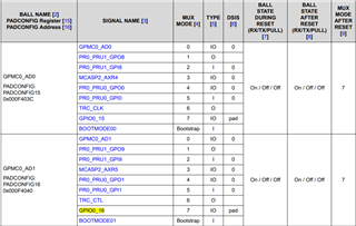
    Update: indeed as the dump showed, the phy is in reset. For our design, we have used pad N23 as phy reset signal. Using the lp-sk dts as the base for our tree, we see that the signal is pulled low. We have not yet found the pinmux config that is resposible for this. On some boards, the pin is used for OSPI CS, but that should not be the case for for SK-LP EVM. I tried to add this pinmux config:

    AM62X_IOPAD(0x0040, PIN_INPUT, 0) /* (N23) GPMC0_AD1 */

    to avoid the reset being driven low, but it does not work. Do you know what cause N23 low?
    If the phy reset is cut, the following dump shows the phy is up and the ethernet works. (though ethernet@8000000port@2 is not listed by mii device):

    Net:   eth0: ethernet@8000000port@1
    Warning: ethernet@8000000port@2 (eth1) using random MAC address - 2a:e7:4b:a5:19:50
    , eth1: ethernet@8000000port@2
    preboot...
    149 bytes read in 9 ms (15.6 KiB/s)
    Importing environment from mmc0 ...
    => mii device
    MII devices: 'mdio@f00' 'ethernet@8000000port@1' 
    Current device: 'mdio@f00'
    => mi device ethernet@8000000port@1
    => mi dump 0 0
    0.     (1000)                 -- PHY control register --
      (8000:0000) 0.15    =     0     reset
      (4000:0000) 0.14    =     0     loopback
      (2040:0000) 0. 6,13 =   b00    speed selection = 10 Mbps
      (1000:1000) 0.12    =     1     A/N enable
      (0800:0000) 0.11    =     0     power-down
      (0400:0000) 0.10    =     0     isolate
      (0200:0000) 0. 9    =     0     restart A/N
      (0100:0000) 0. 8    =     0     duplex = half
      (0080:0000) 0. 7    =     0     collision test enable
      (003f:0000) 0. 5- 0 =     0     (reserved)

    Thanks, Lars

  • Hi Lars,

    For our design, we have used pad N23 as phy reset signal.
    If the phy reset is cut, the following dump shows the phy is up and the ethernet works.

    I checked what N23 is used on the SK-AM62B-EVM as reference and noticed only "k3-am62-lp-sk-nand.dtsi" in U-boot or "k3-am62-lp-sk-nand.dtso" in Linux Kernel dts configured N23 in the pinmux settings. I also tried checking what pin was used for the SK-AM62B-EVM PHY reset but only found the "CPIO_CPSW1_RST" signal is output from an IO expander. The IO expander appears to take an input called RESETSTATz that is comming from a GPIO Interrupt Warm RESET push button.

    AM62X_IOPAD(0x0040, PIN_INPUT, 0) /* (N23) GPMC0_AD1 */

    to avoid the reset being driven low, but it does not work. Do you know what cause N23 low?

    I'm not sure just adding the pinmux config will enable the reset to be driven low. Is there anything (a push button) or software on your custom board that may be affecting the reset signal?

    If the phy reset is cut, the following dump shows the phy is up and the ethernet works. (though ethernet@8000000port@2 is not listed by mii device):

    Can you try running "net list" in U-boot shell and see what shows up?

    The below patch shows details of what I changed on SK-AM62B-EVM to enable the 2nd port to show up in U-boot environment. Please note that this involves changing ONLY "k3-am62x-sk-common-u-boot.dtsi" and keeping "k3-am62x-sk-common.dtsi" unmodified.

    => net list
    eth0 : ethernet@8000000port@1 1c:63:49:0f:61:eb active
    eth1 : ethernet@8000000port@2 70:ff:76:1e:d4:5c

    0001-tested-and-working-2nd-eth-port-in-u-boot.patch

    Perhaps this patch may help you with figuring out why the 2nd port is not listed.

    -Daolin

  • We looked at this issue further,

    1. By default N23 is configured for pinmux mode 7 which is the GPIO mode. If you added the following pinmux setting as you specified above, then is not the correct setting for GPIO mode. You should select for mode 7.

    AM62X_IOPAD(0x0040, PIN_INPUT, 0) /* (N23) GPMC0_AD1 */

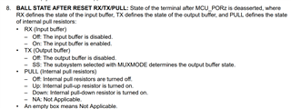
    2. Additionally, the pin ball state after reset is RX=ON, TX=OFF, PULL=OFF. This means it's configured as input GPIO by default. The pin should also be configured as PIN_OUTPUT. 

    3. Is there an external pull down on the reset signal coming from N23? Could you also share a schematic file of how the PHY is setup? 

    4. After steps 1 and 2 above, can you try driving the GPIO signal from N23 low in U-boot command line? The below FAQ gives tips on how to do this.

    https://e2e.ti.com/support/processors-group/processors/f/processors-forum/1398803/faq-processor-sdk-am62x-how-to-toggle-gpios-and-leds-from-u-boot-command-prompt

    -Daolin

  • Hi Daolin,

    Indeed the pinmux mode was wrong, setting mode 7 fixed it. Now the pin is released and is pulled high by an external resistor.

    Also, in u-boot I correctly get two ethernet ports:

    => net list
    eth0 : ethernet@8000000port@1 88:0c:e0:69:a7:3d 
    eth1 : ethernet@8000000port@2 92:f6:c9:97:78:df active

    Thanks and regards,

    Lars