This thread has been locked.

If you have a related question, please click the "Ask a related question" button in the top right corner. The newly created question will be automatically linked to this question.

[FAQ] AM6421: MCSPI CLOCK output not as expected for frequency > 6.25 MHz

Part Number: AM6421
Other Parts Discussed in Thread: SYSCONFIG, AM6442, , AM6422, TMDS64EVM, SK-AM64B

Tool/software:

Hello, 

I found some issues when debugging MCSPI – FRAM. Please help give solutions to resolve these issues, thanks.

Currently below configuration is used for MCSPI0.
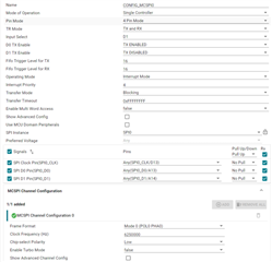
 

The issues are

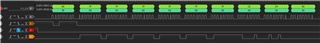
  1. The CLK is not regular or stable, which will cause the data to write or read is NOT correct. (channel 0 is CLK, 1 is SDI, 2 is CS, 3 is SDO)
    1. If CLK is set more than 7M HZ, then the clock output seems not correct as below snapshot. And MCSPI_transfer can NOT write/read correct data in all time.
    2. If CLK is set less than 7M HZ, the clock output is also not regular(duty cycle is variable), in this situation, MCSPI_transfer sometimes can read/write correct data, but it still will read/write error data.


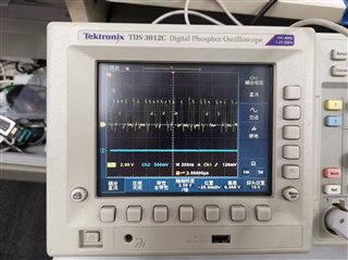
FYI, below snapshot is clock waveform that captured from Oscilloscope.


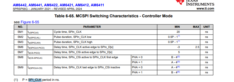
 2. Another point is about MCSPI_Attrs. inputClkFreq, this parameter seems NOT can be configured in sysconfig, it is hard coded as 50M. We want to increase inputClkFreq to see if it can impact CLK output(bring it up to 30M bps)

Can you tell us where to configure it?

/* MCSPI atrributes */

static MCSPI_Attrs gMcspiAttrs[CONFIG_MCSPI_NUM_INSTANCES] =

{

    {

        .baseAddr           = CSL_MCSPI0_CFG_BASE,

        .inputClkFreq       = 50000000U,                // hard coded as 50M. I tried change it manually here, for example, to 200M, but it seems no effect

        .intrNum            = 204,

        .operMode           = MCSPI_OPER_MODE_INTERRUPT,

        .intrPriority       = 4U,

        .chMode             = MCSPI_CH_MODE_SINGLE,

        .pinMode            = MCSPI_PINMODE_4PIN,

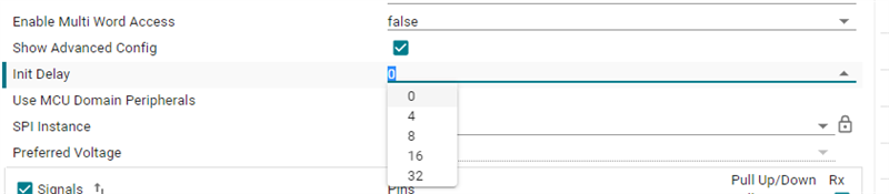
        .initDelay          = MCSPI_INITDLY_0,

        .multiWordAccess    = FALSE,


    },

};

  • Hello,

    Add some information, above test was running on A53 core.

    Additional, example in mcspi_loopback_am64x-sk_r5fss0-0_nortos_ti-arm-clang has been run both on our Demo board and TI Demo board.

    On TI Demo board(AM6442), the test have passed for 8M/10M/50M bps.

    On our Demo board(AM6421), the test have passed for 7M bps, but failed for 8M/50M bps.  

    Case 7M bps

    [MAIN_Cortex_R5_0_0] [MCSPI] Loopback example started ...
    ----------------------------------------------------------
    McSPI Clock 7000000 Hz
    ----------------------------------------------------------
    Data Width Data Length Transfer Time (micro sec)
    8 128 202
    ----------------------------------------------------------

    All tests have passed!!

    Case 8M bps:

    [MAIN_Cortex_R5_0_0] [MCSPI] Loopback example started ...
    ----------------------------------------------------------
    McSPI Clock 8000000 Hz
    ----------------------------------------------------------
    Data Width Data Length Transfer Time (micro sec)
    8 128 179
    ----------------------------------------------------------

    Data Mismatch at offset 16
    Some tests have failed!!

    Case 50M bps:

    [MAIN_Cortex_R5_0_0] [MCSPI] Loopback example started ...
    ----------------------------------------------------------
    McSPI Clock 50000000 Hz
    ----------------------------------------------------------
    Data Width Data Length Transfer Time (micro sec)
    8 128
    ----------------------------------------------------------

    Data Mismatch at offset 4
    Some tests have failed!!

  • Add snapshot for the mcspi_loopback_am64x-sk_r5fss0-0_nortos_ti-arm-clang running on TI Demo Board.

    The duty cycle of CLK(channel 1, 25M Hz) is perfect(50%).

  • The left SPI EEPROM snapshot is captured from TI Demo Board, the right SPI FRAM snapshot is captured from our Demo Board,

    The difference is that SPI CLK is pulled down by our Demo Board, and SPI CLK is pulled up by TI Demo Board.

    I am not sure if it has impact to duty of CLK.  

  • Hi Ling,

    Thank you very much for your patience.

    I will address each one of your issue.

    .inputClkFreq       = 50000000U,                // hard coded as 50M. I tried change it manually here, for example, to 200M, but it seems no effect

    I believe the maximum frequency that can be set is 50 MHz. This can be seen from the attached datasheet information:

    Here is my explanation:

    Minimum is 20 ns which is 50 MHz and you can go further than 20 ns but that means your frequency basically will be <= 50 MHz, so you cannot set it to 200 MHz for sure.

    I have gone through the other replies which you have posted.

    I experimented on the TI EVM as well with different clock frequencies. And it passes for me as well.

    Please see the logs from my experiments with different frequencies.

    [MCSPI] Loopback example started ...
    ----------------------------------------------------------
    McSPI Clock 7000000 Hz
    ----------------------------------------------------------
    Data Width 	Data Length 	Transfer Time (micro sec)
    8		128		205.00
    ----------------------------------------------------------
    
    All tests have passed!!
    [MCSPI] Loopback example started ...
    ----------------------------------------------------------
    McSPI Clock 8000000 Hz
    ----------------------------------------------------------
    Data Width 	Data Length 	Transfer Time (micro sec)
    8		128		179.00
    ----------------------------------------------------------
    
    All tests have passed!!
    [MCSPI] Loopback example started ...
    ----------------------------------------------------------
    McSPI Clock 10000000 Hz
    ----------------------------------------------------------
    Data Width 	Data Length 	Transfer Time (micro sec)
    8		128		138.00
    ----------------------------------------------------------
    
    All tests have passed!!
    [MCSPI] Loopback example started ...
    ----------------------------------------------------------
    McSPI Clock 50000000 Hz
    ----------------------------------------------------------
    Data Width 	Data Length 	Transfer Time (micro sec)
    8		128		59.00
    ----------------------------------------------------------
    
    All tests have passed!!

    So regarding the pull up(on TI EVM) and pull down(on your custom board), I think this should not be a problem, because the 7MHz is passing for you.

    Few questions I need answered:

    1. What is the name of your peripheral? Can you link the datasheet of the peripheral for our reference.
    2. Apart from this have you checked if there is a requirement of some initial delay cycles before the transaction happens? If that is required then it can be set in SysConfig itself as follows:

    Looking forward to your response.

    Regards,

    Vaibhav

  • Hello Vaibhav,

    Thanks for your support.

    The peripheral device is Infineon FM25V10, datasheet is attached for your reference. This device is used in our other projects, it should be OK.

     Infineon-FM25V10_1-Mbit_(128_K_8)_Serial_(SPI)_F-RAM-DataSheet-v12_00-EN.pdf

    Another point, we have tried with taking FRAM off the board and pull up the CLK, it has same test result which will failed if CLK is set more than 7M Hz.

  • Hello Vaibhav,

    I tried Init Delay with 4/8/16/32, it is still failed if CLK > 7M Hz.

  • Hello Vaibhav,

    I tried with AM6422 board, and it passed test with CLK 30M and 50M Hz.

    So the issue seems only happens on AM6421 board.

  • Hello Ling,

    So our next steps should be as follows.

    Since the pull up/pull down of the clock line doubt is eliminated, so we can look at other aspects.

    Can you please go ahead and share with me the MCSPI code snippet for me to go through?

    I believe the code should be the same when you are operating at frequency <7 MHz and > 7 MHz.

    Please share this with me.

    Regards,

    Vaibhav

  • The detail part number is AM6421BSEFHAALVR.


  • The code is same as the example mcspi_loopback_am64x-sk_r5fss0-0_nortos_ti-arm-clang without any change.

    The clock frequency is changed in example.syscfg.

    void *mcspi_loopback_main(void *args)
    {
    int32_t status = SystemP_SUCCESS;
    uint32_t i, j;
    int32_t transferOK;
    MCSPI_Transaction spiTransaction;
    uint32_t startTimeInUSec, elapsedTimeInUsecs;

    Drivers_open();
    Board_driversOpen();

    DebugP_log("[MCSPI] Loopback example started ...\r\n");

    /* Memfill buffers */
    for(i = 0U; i < APP_MCSPI_MSGSIZE; i++)
    {
    gMcspiTxBuffer[i] = i;
    gMcspiRxBuffer[i] = 0U;
    }

    /* Initiate transfer */
    MCSPI_Transaction_init(&spiTransaction);
    spiTransaction.channel = gConfigMcspi0ChCfg[0].chNum;
    spiTransaction.dataSize = 8;
    spiTransaction.csDisable = TRUE;
    spiTransaction.count = APP_MCSPI_MSGSIZE / (spiTransaction.dataSize/8);
    spiTransaction.txBuf = (void *)gMcspiTxBuffer;
    spiTransaction.rxBuf = (void *)gMcspiRxBuffer;
    spiTransaction.args = NULL;
    startTimeInUSec = ClockP_getTimeUsec();
    for(j = 0U; j < APP_MCSPI_TRANSFER_LOOPCOUNT; j++)
    {
    transferOK = MCSPI_transfer(gMcspiHandle[CONFIG_MCSPI0], &spiTransaction);
    }
    elapsedTimeInUsecs = ClockP_getTimeUsec() - startTimeInUSec;

    DebugP_log("----------------------------------------------------------\r\n");
    DebugP_log("McSPI Clock %d Hz\r\n", gConfigMcspi0ChCfg[0U].bitRate);
    DebugP_log("----------------------------------------------------------\r\n");
    DebugP_log("Data Width \tData Length \tTransfer Time (micro sec)\r\n");
    DebugP_log("%u\t\t%u\t\t%5.2f\r\n", spiTransaction.dataSize, APP_MCSPI_MSGSIZE,
    (Float32)(elapsedTimeInUsecs / (uint32_t)APP_MCSPI_TRANSFER_LOOPCOUNT));
    DebugP_log("----------------------------------------------------------\r\n\n");

    if((SystemP_SUCCESS != transferOK) ||
    (MCSPI_TRANSFER_COMPLETED != spiTransaction.status))
    {
    DebugP_assert(FALSE); /* MCSPI transfer failed!! */
    }
    else
    {
    /* Compare data */
    for(i = 0U; i < APP_MCSPI_MSGSIZE; i++)
    {
    if(gMcspiTxBuffer[i] != gMcspiRxBuffer[i])
    {
    status = SystemP_FAILURE; /* Data mismatch */
    DebugP_log("Data Mismatch at offset %d\r\n", i);
    break;
    }
    }
    }

    if(SystemP_SUCCESS == status)
    {
    DebugP_log("All tests have passed!!\r\n");
    }
    else
    {
    DebugP_log("Some tests have failed!!\r\n");
    }

    Board_driversClose();
    Drivers_close();

    return NULL;
    }

  • Ling 

    How have you ruled out board /hardware issues between your 6422 (passing) vs 6421 (failing board) ?

    Is changing the SOC the only change?

    How are you confirming there are no soldering/manufacturing issues - are you seeing this on all 6421 boards (how many built /how many tested and showing failure)?

  • Hello Mukul,

    We cannot 100% make sure that the issue is connected with chip 6421/SDK compatibility as the AM6422 board has different peripheral devices comparing AM6421 board.

    But we did some verifications, which shows that it most likely have no connection to hardware/soldering/manufacturing issues.

    We have tried 3 AM6421 boards, all were failed as same.

    The example code used to test is exactly the same as mcspi_loopback offerred by mcu_plus_sdk_am64x_10_00_00_20\examples\drivers\mcspi. The only change is to configure the CLK to different value by using SYSCFG.

    The example instruction on TI API guide give below description.

    "This example sends a known data in the TX mode of length APP_MCSPI_MSGSIZE and then receives the same in RX mode. Internal pad level loopback mode is enabled to receive data. To enable internal pad level loopback mode, D0 pin is configured to both TX Enable as well as RX input pin in the SYSCFG.

    When transfer is completed, TX and RX buffer data are compared. If data is matched, test result is passed otherwise failed."

    I think the example is configured to use Internal pad level loopback mode, so it should have NO connection to peripheral device or hardware.

    To verify this, we tested with taking peripheral device(FRAM) off the AM6421 board, it was failed as same. We also tried with MCSPI1(another spi channel without any peripheral device connected on AM6421 board) , it was failed as same(failed if CLK > 7M Hz, pass if CLK <=7M Hz).

  • Thanks. Vaibhav will continue to investigate to ensure you do not have a software configuration issue. Again the devices are tested the same way , so the # of core instances (which is different on 6422 and 6421) does not impact SPI coverage and integrity. 

    Is it possible for you to try to populate a 6421 board with a 6422 silicon ? 

  • Hello Mukul,

    We also want to populate a 6421 board with a 6422 silicon. But currently we have no more 6422 silicons and empty 6421 board.

    We already asked product owner to handle this requirement, but it needs much of time to go through the whole process(Apply 6422 material, place order to manufactory, etc.).

    To shorten the time, the same question for you, is it possible for you to try to populate a 6442 TI Demo board with a 6421 silicon?

  • Hello Lin,

    I think the example is configured to use Internal pad level loopback mode, so it should have NO connection to peripheral device or hardware.

    That is a correct understanding.

    To shorten the time, the same question for you, is it possible for you to try to populate a 6442 TI Demo board with a 6421 silicon?

    Allow me sometime to check this internally. Apart from this, I am going to follow up with you in sometime with the next steps.

    Regards,

    Vaibhav

  • Hello Lin

    We do not have any specific demo boards with AM6421, we do the validation initially in bench and product engineering before we offer subset parts and we are confident on the coverage. So while we can also pursue getting samples ordered and put on our EVM to proof this point, the turn around time will maybe slightly smaller, but not by that much. We strongly suspect a hardware issue. In your post you shared the working TI board SPI schematic vs non working SPI 6421 board schematic, can you also share your schematic snapshot for 6422 working board. 

    We will evaluate your request to (re) prove the working on 6421 on a TI demo board, but this will take time. We need to continue to focus on any software/hardware issues that maybe specific to your board. 

    Do you have 6421 silicon and 6422 board (as this board is working) ?

  • Hello Lin,

    For the McSPI interface from the SOC to the FRAM, could you confirm the value of the series resistor on the SPI clock output that is placed near to the SOC.

    I see the FRAM schematics snap shot but cant see the schematics of the SOC side.

    Regards,'

    Sreenivasa

  • Hello Ling,

    Here is a E2E query where a customer was able to successfully run SPI1 on AM6421 silicon.

    E2E: https://e2e.ti.com/support/processors-group/processors/f/processors-forum/1370561/am6421-help-addressing-spi-device-mcp23s17-with-mcspi-driver

    Note the above working was at 20 MHz, which is greater than 7 MHz.

    Meanwhile we review your software configuration, I would encourage you to go through other SPI AM6421 threads as well by searching it on the E2E forum.

    Regards,

    Vaibhav

  • Hello Sreenivasa,

    It seems there is NO resistor on the SPI clock output that is placed neart to the SOC, see below snapshot.

  • Hello Lin,

    Thank you for the inputs.

    The SPI clock is looped back for retiming for the received clock. A series resistor 22 R is recommended. 

    The SPI has read and write IOs and a common output clock. The RXACTIVE is used as a retiming (returning) clock as a reference clock for the internal logic during data read. There is logic internally that loops back the clock and this is activated by RXACTIVE.

    Is there a way you could add the series resistor and perform some tests.

    Please refer below schematics checklist for the recommendations  

    7.4 On-Board Synchronous Communication Interface (MCSPI and I2C)

    7.4.1 Multichannel Serial Peripheral Interface (MCSPI)

    Verify if series resistors (22 Ω) are provided for clock outputs SPI0..4_CLK (MCSPI 0..4) and MCU_SPI0..1_CLK (MCU_MCSPI 0..1) close to processor pins. Verify if external parallel pulls are provided for Chip Select signals SPI0..4_CS0..3 (MCSPI 0..4) & MCU_SPI0..1_CS0..3 (MCSPI 0..1) close to the device pins. Pulls for data outputs are use case dependent and needs to be verified when selecting the attach device.

    Hardware Design Guide
    www.ti.com/.../sprad67a.pdf
    Schematics checklist
    www.ti.com/.../spracu5c.pdf
    DDR Board Design and Layout Guidelines
    www.ti.com/.../spracu1a.pdf
    e2e.ti.com/.../faq-am6442-am6441-am6422-am6421-am6412-am6411-custom-board-hardware-design---faqs-related-to-processor-collaterals-functioning-peripherals-interface-and-evm-starter-kit
    PRU-ICSSG
    www.ti.com/.../sprac90g.pdf

    e2e.ti.com/.../faq-am6442-am6441-am6422-am6421-am6412-am6411-custom-board-hardware-design---design-and-review-notes-for-reuse-of-tmds64evm-schematics
    e2e.ti.com/.../faq-am6442-am6441-am6422-am6421-am6412-am6411-custom-board-hardware-design---design-and-review-notes-for-reuse-of-sk-am64b-schematics
    e2e.ti.com/.../faq-am62x-am64x-custom-board-hardware-design-how-to-handle-used-unused-pins-peripherals-e-g-gpios-serdes-usb-csi-mmc-emmc-sd-card-csi-oldi-dsi

    TMDS64EVM Design Package Folder and Files List
    www.ti.com/.../sprt782
    SK-AM64B Design Package Folder and Files List
    https://www.ti.com/lit/pdf/sprt783

    Regards,

    Sreenivasa

  • Hello Lin,

    I see the clock output in the scope trace above.

    Can you please capture 2..3 cycles in a scope capture and share.

    Regards,

    Sreenivasa

  • Hi Sreenivasa,

    Can you please capture 2..3 cycles in a scope capture and share.

    See below snapshot, I am not very sure if it is what you want. It has 2 CS cycles, failed as it worked at 8M Hz 

  • Hello Lin,

    Thank you.

    I need a scope capture of the clock to view the waveform shape.

    Do you have a way to add a series resistor?

    Regards,

    Sreenivasa

  • Hello Sreenivasa,

    I need a scope capture of the clock to view the waveform shape.

    Do you have a way to add a series resistor?

    I will contact hardware colleague to see if there is way to add a series resistor.

    If it can be added, then I will capture a clock waveform from the Oscilloscope.

  • Hello Mukul,

    In your post you shared the working TI board SPI schematic vs non working SPI 6421 board schematic, can you also share your schematic snapshot for 6422 working board. 

    See below snapshot for 6422 board.

  • Hello Lin,

    Thank you.

    In your post you shared the working TI board SPI schematic vs non working SPI 6421 board schematic, can you also share your schematic snapshot for 6422 working board. 

    See below snapshot for 6422 board.

    Looks like the above schematics follows the design checklist recommendation to include series and parallel resistors.

    Are these 2 different projects, board designs and have hardware changes to be able to swap the SOC?

    Regards,

    Sreenivasa

  • Hello Lin, 

    I will contact hardware colleague to see if there is way to add a series resistor.

    If it can be added, then I will capture a clock waveform from the Oscilloscope.

    Thank you.

    Regards,

    Sreenivasa

  • Hello Sreenivasa,

    We may have no chance to add a series resistor 22 R near the SOC as our hardware engineer pointed out.

    We tried another way, remove the 22 R resistor on 6422 board and run same test. It passed the test with 50M Hz CLK.

    Another point, 2 clock waveforms were captured on 6421 board.

    One is 6.25M Hz as below snapshot.


    Another is 25M Hz as below snapshot

  • Hello Lin, 

    Thank you.

    Another is 25M Hz as below snapshot

    Does the Clock connect to multiple devices - is there any additional trace or load?

    We tried another way, remove the 22 R resistor on 6422 board and run same test. It passed the test with 50M Hz CLK.

    Can you please confirm the pullups and the routings are similar for both the boards.

    We may need schematics details for the 2 boards to verify there are no differences other than the series resistor.

    Regards,

    Sreenivasa

  • Hello All,

    A good news, the issue was found and fixed. It passed loop back test with 50M Hz.

    It is a PCB layout issue as below snapshot, C625 does not connect to GND in PCB layout which lead power supply is not stable.

    Thank you all for great support!

  • Hello Lin, 

    Thank you for the inputs.

    Regards,

    Sreenivasa

  • Hello Lin, 

    Quick note: please be sure to add the series resistor in the next version of the board.

    Regards,

    Sreenivasa