This thread has been locked.

If you have a related question, please click the "Ask a related question" button in the top right corner. The newly created question will be automatically linked to this question.

AM623: Why can serial resistor eliminate eMMC IO error

Part Number: AM623
Other Parts Discussed in Thread: SK-AM62

Tool/software:

In the schematic checklist of eMMC section:

7.2.2.1.1.3 Signals Termination
Provide the following:
• Connect a series resistor (0 Ω) for MMC0_CLK signal (close to processor) and external pulldown resistor for
MMC0_CLK signal (close to eMMC device).
• Connect external pullup resistor for the data line (MMC0_DAT0) (close to eMMC device). eMMC device (as
long as the eMMC device is compliant to the eMMC standard) has the pullups enabled for data signals
MMC0_DAT1..7 by default. The eMMC device will turn off its MMC0_DAT1..3 pulls when entering 4-bit mode
and MMC0_DAT1..7 pulls when entering 8-bit mode. The eMMC host software should turn on the respective
DAT pulls when it changes the mode.

#1. What is the purpose of 0ohm resistor for MMC0_CLK? 

#2. Software turn on DAT pulls when changes the mode, is pulls must required on DAT pins? if so, why eMMC device turn it off from on during switch?

#3. Is it implemented in SDK to turn on DAT pulls when changes mode? did not find padconfig information in driver sdhci_am654.c

  • 1) The series resistor provides an option to install a 10 ohm to 33 ohm impedance to help attenuate reflections that return from the far end of the signal trace if needed to resolve signal integrity issues.

    2) The pull-up resistor R399 is Do Not Install (DNI), so it is not pulled up.

    3) I will need to assign this thread to someone on the software team for this question. Do you have any more questions related to hardware before I reassign?

    Regards,
    Paul

  • Hi Paul,

    Thanks.

    On partial customer boards have CEQ error or IO error, or CRC error, The SDK is old which did not fix tuning algorithm bug. adjust serial resistor on DAT0-7, CMD from 0 to 22ohm resolved the issue, no serial resistor on CMD line. 

    Does it still necessary to update eMMC tuning algorithm to avoid potential CEQ/IO/CRC error in field in future even it passed test before deployed? As it is not a simple decision to update software, so need more detail analysis.

    PS: I assume you were working with software team about the eMMC issue, knew the background of eMMC tuning algorithm update.

  • I'm not sure what was changed with the tuning algorithm bug fix, so I'm not able to answer your question. However, I suspect the change is required to provide a proper data valid window across device operating conditions and it should be implemented to ensure the product works as expected.

    Series resistors are used to resolve signal integrity issues, not resolving timing issues. The series resistors may impact timing just enough to make non-working units work. However, the small timing change that is introduced by the series resistor is typically very small. You should not assume the series resistor is good enough to prevent problems.

    The customer should implement the latest software to have a robust system.

    Regards,
    Paul

  • Hi Paul,

    On this customer's board, the error is triggered by copying specifical data package: originally copying a larger data package >100MB triggered the error/fail, then divide to two equal package, then only one of the two data package trigger error/fail, then divide this package into two equal package again, one of it still can trigger the error, so there is reason to believe the IO/CRC/CQE error is triggered by specific data pattern transmitting on data line which maybe more easy to introduce serious crosstalk, maybe the serial resistor reduced EMI then reduced crosstalk. that is my deduction, if it is reasonable, if optimized tunning process/algorithm can improve the anti-interference capability?

  • The issue could be related to crosstalk or ISI.

    There is a good chance the failing data pattern is creating a standing wave on one or more of the data signals due to reflections and the standing wave interferes with subsequent data patterns. This is commonly called intersymbol interference (ISI), which is a form of signal distortion in which one symbol interferes with subsequent symbols.

    Installing a series resistor could attenuate any reflections and effectively kill the standing wave before it creates a problem.

    Your customer should be performing a signal integrity simulation on the PCB layout that checks for any crosstalk or ISI issue. Did they perform any signal integrity simulations while designing their PCB?

    I suggest you work with Bin to print the tuning algorithm log and see if it is selecting a capture point that is centered in the data valid window. The problem could be a signal integrity issue if the tuning algorithm is selecting a capture point that is centered in the data valid window. If so, the series resistors may be the only solution.

    Regards,
    Paul

  • Hi Paul,

    Is tunning adjust clock phase or data signal phase?

  • Tuning is used in HS200 mode to optimize receive timing. This is needed because the attached eMMC devices doesn't provide a data strobe (DS) signal during HS200 mode. We need to compensate for the PCB and attached eMMC delays that vary across systems so the capture clock transition can be centered in the data valid window. The delay being adjusted during tuning is in the receiver DAT/CMD capture clock inside the AM62x device.

    Regards,
    Paul

  • Hi Paul,

    Thanks. 

    If tuning adjust DAT/CMD other than clock, then each DAT/CMD line should have different delay, from log, seems all signal shares one ITAP delay value, so the equal length is very important for layout? 

  • The respective datasheet Timing Conditions table defines the maximum PCB delay mismatch allowed for each data transfer mode. Our design team accounts for this PCB trace delay mismatch during timing closure of the peripheral.

  • Your customer should be performing a signal integrity simulation on the PCB layout that checks for any crosstalk or ISI issue.

    Is there method to capture or simulate ISI?

  • I'm going to reassign this thread to someone that is able to discuss this topic in more detail than me.

    Regards,
    Paul

  • Hi Paul,

    After boot from eMMC on SK-AM62, the padconfig value are 0x50000, which shows eMMC pin pulls are disabled and receiver enabled. it violated the statement from schematic check list:

    "The eMMC device will turn off its MMC0_DAT1..3 pulls when entering 4-bit mode and MMC0_DAT1..7 pulls when entering 8-bit mode. The eMMC host software should turn on the respective DAT pulls when it changes the mode."

    root@am62xx-evm:~# devmem2 0x000f4210
    /dev/mem opened.
    Memory mapped at address 0xffffba25c000.
    Read at address  0x000F4210 (0xffffba25c210): 0x00050000
    root@am62xx-evm:~# devmem2 0x000f4214
    /dev/mem opened.
    Memory mapped at address 0xffffb1ed8000.
    Read at address  0x000F4214 (0xffffb1ed8214): 0x00050000
    root@am62xx-evm:~# devmem2 0x000f420c
    /dev/mem opened.
    Memory mapped at address 0xffffba365000.
    Read at address  0x000F420C (0xffffba36520c): 0x00050000
    root@am62xx-evm:~# devmem2 0x000f4208
    /dev/mem opened.
    Memory mapped at address 0xffff88912000.
    Read at address  0x000F4208 (0xffff88912208): 0x00050000
    root@am62xx-evm:~# devmem2 0x000f4204
    /dev/mem opened.
    Memory mapped at address 0xffff910f7000.
    Read at address  0x000F4204 (0xffff910f7204): 0x00050000
    root@am62xx-evm:~# devmem2 0x000f4200
    /dev/mem opened.
    Memory mapped at address 0xffff87f2e000.
    Read at address  0x000F4200 (0xffff87f2e200): 0x00050000
    root@am62xx-evm:~# devmem2 0x000f41FC
    /dev/mem opened.
    Memory mapped at address 0xffff8e8a6000.
    Read at address  0x000F41FC (0xffff8e8a61fc): 0x00050000
    root@am62xx-evm:~# devmem2 0x000f41F8
    /dev/mem opened.
    Memory mapped at address 0xffff8a0e3000.
    Read at address  0x000F41F8 (0xffff8a0e31f8): 0x00050000
    root@am62xx-evm:~# uname -a
    Linux am62xx-evm 6.1.80-dirty #4 SMP PREEMPT Fri May  9 17:14:06 CST 2025 aarch64 aarch64 aarch64 GNU/Linux
    root@am62xx-evm:

  • If so, this is a software bug that could impact long-term reliability of the AM62x and eMMC devices by allowing the signals to float when not driven.

    You should file a bug to highlight this issue.

    Regards,
    Paul

  • Attaching some documentation on ISI which can help address this question.ISI_SSO_basics.pptx

  • Hi Shriram,

    I understand there are two type interference described in the slides:

    #1. SSO: supply switch noise of worst case when switch simultaneously.

    #2. ISI: caused by reflections by impedance mismatch.

    For this customer's case, replace serial resistor from 0ohm to 22ohm/33ohm eliminated eMMC IO/CRC/CQE error on boards which can reproduce definitely when with 0ohm resistor.

    By probing signal, there is not obviously change to signal quality with either resistor value.

    How do you think if it related to SSO or ISI?

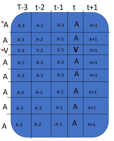
    BTW: What is A and V stands for here? in the table

  • Tony, The A in the table stands for aggressor while V stands for victim. I am not clear about the statement regarding how replacing the resistor value impacted the error observed. Regarding SSO vs ISI, it is pattern specific. Worst case SSO will be excited by simultaneous switching of all signals. Worst case ISI will be excited by switching a data bit from a long stream of 0s to a 1 and then back to 0 in the next cycle. So a long stream of 0s followed by 0101 type switching. Vice versa for the opposite logic state as well.

    -Shriram 

  • If so, this is a software bug that could impact long-term reliability of the AM62x and eMMC devices by allowing the signals to float when not driven.

    You should file a bug to highlight this issue.

    I am not sure if it is talking about the pull ups inside eMMC for software to control, and not sure if it is really enabled. not sure who can comment it.