This thread has been locked.

If you have a related question, please click the "Ask a related question" button in the top right corner. The newly created question will be automatically linked to this question.

AM62P: MCU_MCAN communication with external CAN sources

Part Number: AM62P
Other Parts Discussed in Thread: SN65HVD230, SYSCONFIG

Tool/software:

Hello Support Team,

I'm trying to establish CAN communication between the MCAN_0 (MCU_R5 core) on the AM62P-LP board and an Innomaker USB2CAN module connected to my Linux host. I followed the steps from the TI E2E guide:
FAQ - SK-AM62x MCAN External Loopback, tried all software changes advised in the thread ,but it's not working.

Hardware:

  1. AM62P-LP Board

  2. SN65HVD230 CAN Transceiver

  3. DB9 Connector

  4. Innomaker USB2CAN Module

Connections:

  • D6 (pin 22, MCU header) → RX of CAN transceiver

  • E8 (pin 16, MCU header) → TX of CAN transceiver

  • Pin 1 (MCU header) → 3.3V (CAN transceiver)

  • Pin 2 (MCU header) → GND (CAN transceiver)

  • Pin 3 (MCU header) → GND (DB9 connector, pin 3)

  • CANL (transceiver) → DB9 pin 2

  • CANH (transceiver) → DB9 pin 7

  • DB9 connected to USB2CAN module, then to Linux host

Issue:
I attempted to send CAN frames from the host using cansend. The interface is set to 5 Mbps, but communication is not working.

Please advise on what could be going wrong or suggest any debugging steps.

Thanks,
Abhishek S S

  • Hi Abhishek,

    I attempted to send CAN frames from the host using cansend. The interface is set to 5 Mbps, but communication is not working.

    Could you elaborate the issue further? Could you try to debug the application using CCS and tell me where exactly the code flow is stuck, please share the UART logs from the applications as well if they indicate any issues.

    The loopback example also has a Tx part, do you at least see the data being received properly via your USB2CAN, as the shared FAQ mentions, after successful reception of data, the data has to be transmitted ten times from the CAN analyzer/tool for test to end.

    Best Regards,

    Meet.

  • Hello Meet,

    Could you elaborate the issue further?

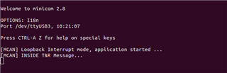
    Sure. So I am trying to flash mcan_loopback_interrupt_am62px-sk_mcu-r5fss0-0_freertos_ti-arm-clang example application in external mode in ospi boot mode. And I have changed the software requirements which is -> App_mcanConfig(FALSE); as per the FAQ. This is the log which I am getting -> 

    Could you try to debug the application using CCS and tell me where exactly the code flow is stuck, please share the UART logs from the applications as well if they indicate any issues


    I have not tried debugging the applica
    tion yet. Will try it and get back to you.

    The loopback example also has a Tx part, do you at least see the data being received properly via your USB2CAN, as the shared FAQ mentions, after successful reception of data, the data has to be transmitted ten times from the CAN analyzer/tool for test to end.

    No, the data is not received using USB2CAN module as well. But I can assure you that the USB2CAN is in perfect working condition, since I used it for different experiment.

  • Could you try to debug the application using CCS and tell me where exactly the code flow is stuck, please share the UART logs from the applications as well if they indicate any issues

    Hello Meet,
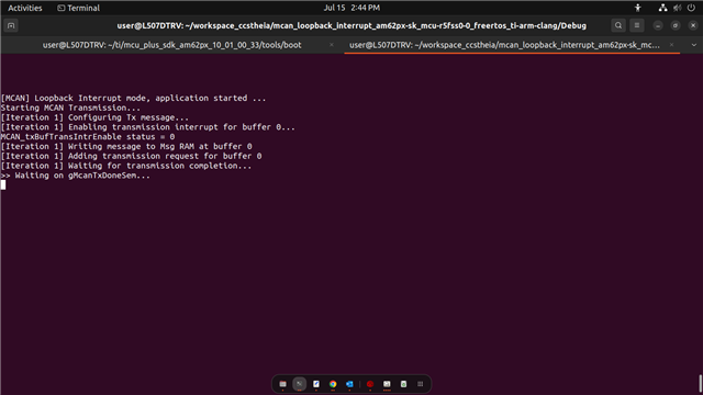
    I have tried debugging the code using DebugP_log() and i found out that the code is stuck at SemaphoreP_pend(&gMcanTxDoneSem, SystemP_WAIT_FOREVER);
    I will provide the whole code, so that you can understand the debugging pattern i used and will also provide the log after flashing the application.

    #include <stdio.h>
    #include <kernel/dpl/DebugP.h>
    #include <kernel/dpl/AddrTranslateP.h>
    #include <kernel/dpl/SemaphoreP.h>
    #include <drivers/mcan.h>
    #include "ti_drivers_config.h"
    #include "ti_drivers_open_close.h"
    #include "ti_board_open_close.h"
    
    #define APP_MCAN_BASE_ADDR                       (CONFIG_MCAN0_BASE_ADDR)
    #define APP_MCAN_INTR_NUM                        (CONFIG_MCAN0_INTR)
    #define APP_MCAN_MSG_LOOP_COUNT                  (10U)
    
    /* Allocate Message RAM memory section to filter elements, buffers, FIFO */
    /* Maximum STD Filter Element can be configured is 128 */
    #define APP_MCAN_STD_ID_FILTER_CNT               (1U)
    /* Maximum EXT Filter Element can be configured is 64 */
    #define APP_MCAN_EXT_ID_FILTER_CNT               (0U)
    /* Maximum TX Buffer + TX FIFO, combined can be configured is 32 */
    #define APP_MCAN_TX_BUFF_CNT                     (1U)
    #define APP_MCAN_TX_FIFO_CNT                     (0U)
    /* Maximum TX Event FIFO can be configured is 32 */
    #define APP_MCAN_TX_EVENT_FIFO_CNT               (0U)
    /* Maximum RX FIFO 0 can be configured is 64 */
    #define APP_MCAN_FIFO_0_CNT                      (0U)
    /* Maximum RX FIFO 1 can be configured is 64 and
     * rest of the memory is allocated to RX buffer which is again of max size 64 */
    #define APP_MCAN_FIFO_1_CNT                      (0U)
    
    /* Standard Id configured in this app */
    #define APP_MCAN_STD_ID                          (0xC0U)
    #define APP_MCAN_STD_ID_MASK                     (0x7FFU)
    #define APP_MCAN_STD_ID_SHIFT                    (18U)
    
    #define APP_MCAN_EXT_ID_MASK                     (0x1FFFFFFFU)
    
    /* In the CAN FD format, the Data length coding differs from the standard CAN.
     * In case of standard CAN it is 8 bytes */
    static const uint8_t gMcanDataSize[16U] = {0U,  1U,  2U,  3U,
                                               4U,  5U,  6U,  7U,
                                               8U,  12U, 16U, 20U,
                                               24U, 32U, 48U, 64U};
    
    /* Semaphore to indicate transfer completion */
    static SemaphoreP_Object gMcanTxDoneSem, gMcanRxDoneSem;
    static HwiP_Object       gMcanHwiObject;
    static uint32_t          gMcanBaseAddr;
    
    /* Static Function Declarations */
    static void    App_mcanIntrISR(void *arg);
    static void    App_mcanConfig(Bool enableInternalLpbk);
    static void    App_mcanInitMsgRamConfigParams(
                   MCAN_MsgRAMConfigParams *msgRAMConfigParams);
    static void    App_mcanEnableIntr(void);
    static void    App_mcanConfigTxMsg(MCAN_TxBufElement *txMsg);
    static void    App_mcanCompareMsg(MCAN_TxBufElement *txMsg,
                                      MCAN_RxBufElement *rxMsg);
    static void    App_mcanInitStdFilterElemParams(
                                      MCAN_StdMsgIDFilterElement *stdFiltElem,
                                      uint32_t bufNum);
    
    void mcan_loopback_interrupt_main(void *args)
    {
        int32_t                 status = SystemP_SUCCESS;
        HwiP_Params             hwiPrms;
        MCAN_TxBufElement       txMsg;
        MCAN_ProtocolStatus     protStatus;
        MCAN_RxBufElement       rxMsg;
        MCAN_RxNewDataStatus    newDataStatus;
        MCAN_ErrCntStatus       errCounter;
        uint32_t                i, bufNum, fifoNum, bitPos = 0U;
    
        DebugP_log("[MCAN] Loopback Interrupt mode, application started ...\r\n");
    
        /* Construct Tx/Rx Semaphore objects */
        status = SemaphoreP_constructBinary(&gMcanTxDoneSem, 0);
        DebugP_assert(SystemP_SUCCESS == status);
        status = SemaphoreP_constructBinary(&gMcanRxDoneSem, 0);
        DebugP_assert(SystemP_SUCCESS == status);
    
        /* Register interrupt */
        HwiP_Params_init(&hwiPrms);
        hwiPrms.intNum      = APP_MCAN_INTR_NUM;
        hwiPrms.callback    = &App_mcanIntrISR;
        status              = HwiP_construct(&gMcanHwiObject, &hwiPrms);
        HwiP_enable();
        DebugP_assert(status == SystemP_SUCCESS);
    
        /* Assign MCAN instance address */
        gMcanBaseAddr = (uint32_t) AddrTranslateP_getLocalAddr(APP_MCAN_BASE_ADDR);
    
        /* Configure MCAN module, Enable LoopBack Mode */
        App_mcanConfig(FALSE);
    
        /* Enable Interrupts */
        App_mcanEnableIntr();
    
        /* Transmit And Receive Message */
    
        DebugP_log("Starting MCAN Transmission...\r\n");
    
        for (i = 0U; i < APP_MCAN_MSG_LOOP_COUNT; i++)
        {
            /* Configure Tx Msg to transmit */
            DebugP_log("[Iteration %u] Configuring Tx message...\r\n", i + 1);
    
            App_mcanConfigTxMsg(&txMsg);
    
            /* Select buffer number, 32 buffers available */
            bufNum = 0U;
            DebugP_log("[Iteration %u] Enabling transmission interrupt for buffer %u...\r\n", i + 1, bufNum);
    
            /* Enable Transmission interrupt for the selected buf num,
             * If FIFO is used, then need to send FIFO start index until FIFO count */
            status = MCAN_txBufTransIntrEnable(gMcanBaseAddr, bufNum, (uint32_t)TRUE);
            DebugP_log("MCAN_txBufTransIntrEnable status = %d\r\n", status);
            DebugP_assert(status == CSL_PASS);
            DebugP_log("[Iteration %u] Writing message to Msg RAM at buffer %u\r\n", i + 1, bufNum);
    
            /* Write message to Msg RAM */
            MCAN_writeMsgRam(gMcanBaseAddr, MCAN_MEM_TYPE_BUF, bufNum, &txMsg);
            DebugP_log("[Iteration %u] Adding transmission request for buffer %u\r\n", i + 1, bufNum);
    
            /* Add request for transmission, This function will trigger transmission */
            status = MCAN_txBufAddReq(gMcanBaseAddr, bufNum);
            DebugP_assert(status == CSL_PASS);
            DebugP_log("[Iteration %u] Waiting for transmission completion...\r\n", i + 1);
    
            DebugP_log(">> Waiting on gMcanTxDoneSem...\r\n");
            SemaphoreP_pend(&gMcanTxDoneSem, SystemP_WAIT_FOREVER);
            DebugP_log("<< Unblocked from gMcanTxDoneSem\r\n");
    
            MCAN_getProtocolStatus(gMcanBaseAddr, &protStatus);
             DebugP_log("[Iteration %u] Transmission complete.\r\n", i + 1);
             DebugP_log("  Protocol Status:\r\n");
             DebugP_log("    Last Error Code: %u\r\n", protStatus.lastErrCode);
             DebugP_log("    Data Last Error Code: %u\r\n", protStatus.dlec);
             DebugP_log("    Protocol Exception Event: %u\r\n", protStatus.pxe);
    
            /* Checking for Tx Errors */
            if (((MCAN_ERR_CODE_NO_ERROR != protStatus.lastErrCode) ||
                 (MCAN_ERR_CODE_NO_CHANGE != protStatus.lastErrCode)) &&
                ((MCAN_ERR_CODE_NO_ERROR != protStatus.dlec) ||
                 (MCAN_ERR_CODE_NO_CHANGE != protStatus.dlec)) &&
                (0U != protStatus.pxe))
            {   
                DebugP_log("[Iteration %u] ERROR: Transmission error detected!\r\n", i + 1);
    
                DebugP_assert(FALSE);
            }
    
            /* Wait for Rx completion */
            SemaphoreP_pend(&gMcanRxDoneSem, SystemP_WAIT_FOREVER);
    
            /* Checking for Rx Errors */
            MCAN_getErrCounters(gMcanBaseAddr, &errCounter);
            DebugP_assert((0U == errCounter.recErrCnt) &&
                          (0U == errCounter.canErrLogCnt));
    
            /* Get the new data staus, indicates buffer num which received message */
            MCAN_getNewDataStatus(gMcanBaseAddr, &newDataStatus);
            MCAN_clearNewDataStatus(gMcanBaseAddr, &newDataStatus);
    
            /* Select buffer and fifo number, Buffer is used in this app */
            bufNum = 0U;
            fifoNum = MCAN_RX_FIFO_NUM_0;
    
            bitPos = (1U << bufNum);
            if (bitPos == (newDataStatus.statusLow & bitPos))
            {
                MCAN_readMsgRam(gMcanBaseAddr, MCAN_MEM_TYPE_BUF, bufNum, fifoNum, &rxMsg);
            }
            else
            {
                DebugP_assert(FALSE);
            }
    
            /* Compare Tx/Rx data */
            App_mcanCompareMsg(&txMsg, &rxMsg);
        }
        /* De-Construct Tx/Rx Semaphore objects */
        HwiP_destruct(&gMcanHwiObject);
        SemaphoreP_destruct(&gMcanTxDoneSem);
        SemaphoreP_destruct(&gMcanRxDoneSem);
    
        DebugP_log("All tests have passed!!\r\n");
    
        return;
    }
    
    static void App_mcanConfig(Bool enableInternalLpbk)
    {
        MCAN_StdMsgIDFilterElement stdFiltElem[APP_MCAN_STD_ID_FILTER_CNT] = {0U};
        MCAN_InitParams            initParams = {0U};
        MCAN_ConfigParams          configParams = {0U};
        MCAN_MsgRAMConfigParams    msgRAMConfigParams = {0U};
        MCAN_BitTimingParams       bitTimes = {0U};
        uint32_t                   i;
    
        /* Initialize MCAN module initParams */
        MCAN_initOperModeParams(&initParams);
        /* CAN FD Mode and Bit Rate Switch Enabled */
        initParams.fdMode          = TRUE;
        initParams.brsEnable       = TRUE;
    
        /* Initialize MCAN module Global Filter Params */
        MCAN_initGlobalFilterConfigParams(&configParams);
    
        /* Initialize MCAN module Bit Time Params */
        /* Configuring default 1Mbps and 5Mbps as nominal and data bit-rate resp */
        MCAN_initSetBitTimeParams(&bitTimes);
    
        /* Initialize MCAN module Message Ram Params */
        App_mcanInitMsgRamConfigParams(&msgRAMConfigParams);
    
        /* Initialize Filter element to receive msg, should be same as tx msg id */
        for (i = 0U; i < APP_MCAN_STD_ID_FILTER_CNT; i++)
        {
            App_mcanInitStdFilterElemParams(&stdFiltElem[i], i);
        }
        /* wait for memory initialization to happen */
        while (FALSE == MCAN_isMemInitDone(gMcanBaseAddr))
        {}
    
        /* Put MCAN in SW initialization mode */
        MCAN_setOpMode(gMcanBaseAddr, MCAN_OPERATION_MODE_SW_INIT);
        while (MCAN_OPERATION_MODE_SW_INIT != MCAN_getOpMode(gMcanBaseAddr))
        {}
    
        /* Initialize MCAN module */
        MCAN_init(gMcanBaseAddr, &initParams);
        /* Configure MCAN module Gloabal Filter */
        MCAN_config(gMcanBaseAddr, &configParams);
        /* Configure Bit timings */
        MCAN_setBitTime(gMcanBaseAddr, &bitTimes);
        /* Configure Message RAM Sections */
        MCAN_msgRAMConfig(gMcanBaseAddr, &msgRAMConfigParams);
        /* Set Extended ID Mask */
        MCAN_setExtIDAndMask(gMcanBaseAddr, APP_MCAN_EXT_ID_MASK);
    
        /* Configure Standard ID filter element */
        for (i = 0U; i < APP_MCAN_STD_ID_FILTER_CNT; i++)
        {
            MCAN_addStdMsgIDFilter(gMcanBaseAddr, i, &stdFiltElem[i]);
        }
        if (TRUE == enableInternalLpbk)
        {
            MCAN_lpbkModeEnable(gMcanBaseAddr, MCAN_LPBK_MODE_INTERNAL, TRUE);
        }
    
        /* Take MCAN out of the SW initialization mode */
        MCAN_setOpMode(gMcanBaseAddr, MCAN_OPERATION_MODE_NORMAL);
        while (MCAN_OPERATION_MODE_NORMAL != MCAN_getOpMode(gMcanBaseAddr))
        {}
    
        return;
    }
    
    static void App_mcanConfigTxMsg(MCAN_TxBufElement *txMsg)
    {
        uint32_t i;
    
        /* Initialize message to transmit */
        MCAN_initTxBufElement(txMsg);
        /* Standard message identifier 11 bit, stored into ID[28-18] */
        txMsg->id  = ((APP_MCAN_STD_ID & MCAN_STD_ID_MASK) << MCAN_STD_ID_SHIFT);
        txMsg->dlc = MCAN_DATA_SIZE_64BYTES; /* Payload size is 64 bytes */
        txMsg->fdf = TRUE; /* CAN FD Frame Format */
        txMsg->xtd = FALSE; /* Extended id not configured */
        for (i = 0U; i < gMcanDataSize[MCAN_DATA_SIZE_64BYTES]; i++)
        {
            txMsg->data[i] = i;
        }
    
        return;
    }
    
    static void App_mcanInitStdFilterElemParams(MCAN_StdMsgIDFilterElement *stdFiltElem,
                                                uint32_t bufNum)
    {
        /* sfid1 defines the ID of the standard message to be stored. */
        stdFiltElem->sfid1 = APP_MCAN_STD_ID;
        /* As buffer mode is selected, sfid2 should be bufNum[0 - 63] */
        stdFiltElem->sfid2 = bufNum;
        /* Store message in buffer */
        stdFiltElem->sfec  = MCAN_STD_FILT_ELEM_BUFFER;
        /* Below configuration is ignored if message is stored in buffer */
        stdFiltElem->sft   = MCAN_STD_FILT_TYPE_RANGE;
    
        return;
    }
    
    static void App_mcanEnableIntr(void)
    {
        MCAN_enableIntr(gMcanBaseAddr, MCAN_INTR_MASK_ALL, (uint32_t)TRUE);
        MCAN_enableIntr(gMcanBaseAddr,
                        MCAN_INTR_SRC_RES_ADDR_ACCESS, (uint32_t)FALSE);
        /* Select Interrupt Line 0 */
        MCAN_selectIntrLine(gMcanBaseAddr, MCAN_INTR_MASK_ALL, MCAN_INTR_LINE_NUM_0);
        /* Enable Interrupt Line */
        MCAN_enableIntrLine(gMcanBaseAddr, MCAN_INTR_LINE_NUM_0, (uint32_t)TRUE);
    
        return;
    }
    
    static void App_mcanInitMsgRamConfigParams(MCAN_MsgRAMConfigParams
                                               *msgRAMConfigParams)
    {
        int32_t status;
    
        MCAN_initMsgRamConfigParams(msgRAMConfigParams);
    
        /* Configure the user required msg ram params */
        msgRAMConfigParams->lss = APP_MCAN_STD_ID_FILTER_CNT;
        msgRAMConfigParams->lse = APP_MCAN_EXT_ID_FILTER_CNT;
        msgRAMConfigParams->txBufCnt = APP_MCAN_TX_BUFF_CNT;
        msgRAMConfigParams->txFIFOCnt = APP_MCAN_TX_FIFO_CNT;
        /* Buffer/FIFO mode is selected */
        msgRAMConfigParams->txBufMode = MCAN_TX_MEM_TYPE_BUF;
        msgRAMConfigParams->txEventFIFOCnt = APP_MCAN_TX_EVENT_FIFO_CNT;
        msgRAMConfigParams->rxFIFO0Cnt = APP_MCAN_FIFO_0_CNT;
        msgRAMConfigParams->rxFIFO1Cnt = APP_MCAN_FIFO_1_CNT;
        /* FIFO blocking mode is selected */
        msgRAMConfigParams->rxFIFO0OpMode = MCAN_RX_FIFO_OPERATION_MODE_BLOCKING;
        msgRAMConfigParams->rxFIFO1OpMode = MCAN_RX_FIFO_OPERATION_MODE_BLOCKING;
    
        status = MCAN_calcMsgRamParamsStartAddr(msgRAMConfigParams);
        DebugP_assert(status == CSL_PASS);
    
        return;
    }
    
    static void App_mcanCompareMsg(MCAN_TxBufElement *txMsg,
                                   MCAN_RxBufElement *rxMsg)
    {
        uint32_t i;
    
        if (((txMsg->id >> APP_MCAN_STD_ID_SHIFT) & APP_MCAN_STD_ID_MASK) ==
                ((rxMsg->id >> APP_MCAN_STD_ID_SHIFT) & APP_MCAN_STD_ID_MASK))
        {
            for (i = 0U; i < gMcanDataSize[MCAN_DATA_SIZE_64BYTES]; i++)
            {
                if (txMsg->data[i] != rxMsg->data[i])
                {
                    DebugP_logError("Data mismatch !!!\r\n");
                    DebugP_assert(FALSE);
                }
            }
        }
        else
        {
            DebugP_logError("Message ID mismatch !!!\r\n");
            DebugP_assert(FALSE);
        }
    
        return;
    }
    
    static void App_mcanIntrISR(void *arg)
    {
        uint32_t intrStatus;
    
        intrStatus = MCAN_getIntrStatus(gMcanBaseAddr);
        DebugP_log("ISR: intrStatus = 0x%08X\r\n", intrStatus);
        MCAN_clearIntrStatus(gMcanBaseAddr, intrStatus);
    
        // if (MCAN_INTR_SRC_TRANS_COMPLETE ==
        //     (intrStatus & MCAN_INTR_SRC_TRANS_COMPLETE))
        if ((intrStatus & MCAN_INTR_SRC_TRANS_COMPLETE) != 0U)
        {
            DebugP_log("<< ISR: Tx Complete interrupt received, posting Tx semaphore\r\n");
            SemaphoreP_post(&gMcanTxDoneSem);
        }
    
        /* If FIFO0/FIFO1 is used, then MCAN_INTR_SRC_DEDICATED_RX_BUFF_MSG macro
         * needs to be replaced by MCAN_INTR_SRC_RX_FIFO0_NEW_MSG/
         * MCAN_INTR_SRC_RX_FIFO1_NEW_MSG respectively */
        // if (MCAN_INTR_SRC_DEDICATED_RX_BUFF_MSG ==
        //     (intrStatus & MCAN_INTR_SRC_DEDICATED_RX_BUFF_MSG))
        if ((intrStatus & MCAN_INTR_SRC_DEDICATED_RX_BUFF_MSG) != 0U)
        {
            DebugP_log("<< ISR: Rx interrupt received, posting Rx semaphore\r\n");
            SemaphoreP_post(&gMcanRxDoneSem);
        }
    
        return;
    }


    Best Regards,
    Abhishek 

  • Hi Abhishek,

    From the logs you shared it seems that the transmission itself was not successful, indicating that USB2CAN module was not able to receive the messages. I don't see any issues with the code as you have taken care of what is mentioned in the shared FAQ, as the example is now stuck in the transmission itself it, you won't be able to proceed further to the Rx part and send messages from USB2CAN module.

    Please make sure that the bitrate and the sampling point is properly set in your innomaker software.

    Best Regards,

    Meet.

  • Hi Meet,

    Initially, I set the bitrate to 5 Mbps based on the information provided in the FAQ. The command I used on my Linux machine to bring up the Innomaker CAN module was:
    sudo ip link set can0 up type can bitrate 5000000. 

    However, since it's not working, I plan to verify whether the bitrate and sampling point I’ve configured are correct.

    According to the FAQ -> the bitrate and sampling point are calculated using the following formulas:

    • Bitrate (bps) = (CAN clock in Hz) / BRP / (1 + TSEG1 + TSEG2)

    • Sampling Point (%) = (1 + TSEG1) / (1 + TSEG1 + TSEG2)

    (Note: The values configured in SysConfig or the structure are directly written to the MCAN register bit fields. The hardware interprets these values as one more than what is programmed.)

    In FAQ this example was also given, the default values used for nominal bitrate are:

    • MCAN_BitTimingParams::nomRatePrescalar = 7 (so BRP = 8)

    • MCAN_BitTimingParams::nomTimeSeg1 = 12 (so TSEG1 = 13)

    • MCAN_BitTimingParams::nomTimeSeg2 = 5 (so TSEG2 = 6)

    Using these values:
    Bitrate = 80 MHz / 8 / (1 + 13 + 6) = 0.5 Mbps

    I have a couple of doubts:

    1. How can I find the value of the CAN clock (in Hz)?

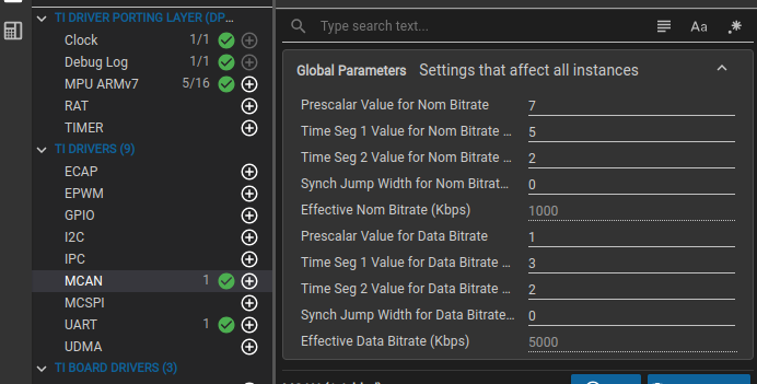
    2. In the example.sys file, I found the values for BRP, TSEG1, and TSEG2. I’ve also attached a screenshot for reference. Based on that, should I interpret the values as:

      • BRP = 8

      • TSEG1 = 6

      • TSEG2 = 3
        (Considering the "+1" interpretation by the hardware)?

    Please let me know if my understanding is correct.

    Best regards,
    Abhishek


  • HI  Abhishek,

    How can I find the value of the CAN clock (in Hz)?

    By default, the frequency of CAN module set is 80MHz, you can refer to this clock tree tool and check how the frequency for MCAN module is derived: SysConfig

    In the example.sys file, I found the values for BRP, TSEG1, and TSEG2. I’ve also attached a screenshot for reference.

    Your interpretation is correct.

    Best Regards,

    Meet.

  • Hi Meet,

    The transmission is still not completing — the program appears to be stuck at the same line as before.

    Based on my current configuration, the calculated bit-rate is 1 Mbps, and the sampling point is 0.7.

    As a reference, I have attached a screenshot showing that the Innomaker USB2CAN module is also brought up with the same configuration.

    Could you please take a look and advise if there’s anything else I might be missing?

    Best Regards,
    Abhishek

  • Hi Abhishek,

    The example uses the CAN-FD module, It seems that your USB2CAN module doen't support CAN-FD could you please confirm the same?

    Best Regards,

    Meet.

  • Hello Meet, 

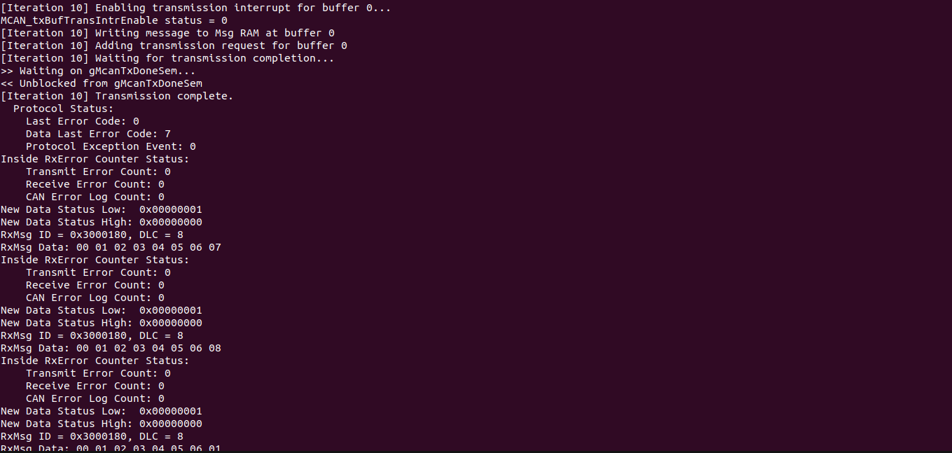
    I wanted to let you know that I resolved the issue last Friday. The problem was with the USB2CAN module — it doesn’t support CAN-FD and only transmits data at a rate of 1 Mbps. After adjusting the code accordingly, everything worked perfectly.

    I’ve attached some screenshots for your reference.

    It’s great to see that you were also able to crack it in the end!
    Thanks!

    Best Regards,
    Abhishek 

  • Hi Abhishek,

    Thanks for the update, glad to know that your issue is resolved now.

    Best Regards,

    Meet.