


Other Parts Discussed in Thread: TMS320F28335,
Tool/software:
Hi TI Experts,
We are developing an SPI communication link between an AM3352 (ARM, as SPI master) and a TMS320F28335 (DSP, as SPI slave).
All SPI signal line pull-up and pull-down settings use the internal configuration of each chip only; there are no external resistors on the board.
1. Current Configuration
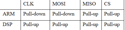
• SPI master: AM3352, slave: F28335
• Typical SPI speed: 1.5 MHz
• All pull-up/down: internal only (no external resistors)
2. Questions
• Is this pull-up/pull-down configuration correct and robust for ARM master to DSP slave connection?
• Is there an official or recommended best practice from TI regarding SPI pull-up/pull-down resistor settings for this scenario?
• Can improper internal pull-up/down settings cause data misalignment or communication problems, especially at power-up?
• Should any lines (such as unused pins) be configured differently?
3. Issue
• With this setup, we occasionally see data misalignment or lost communication after power-on.
• We want to make sure the pull-up/down settings are correct on both sides.
Any official guidance or reference schematic would be greatly appreciated.
Thank you for your support!
Best regards,
[Zhou zhou/Kangni]
