Part Number: J721EXSOMG01EVM
Tool/software:
First how we have things setup.
Using ti-processor-sdk-linux-adas-j721e-evm11_00_00_00_08. Built kernel using YOCTO, burned to SD card and booted. Removed to soft links to all other processors executables except for mcu1_0 which I left running ipc_echo_test.
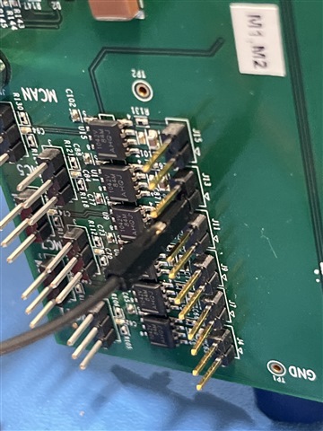
Have the EVM main board wtih a J721ESOM as well as the Quad Ethernet and GESI expander baord.
We have sucessfully use the R5F processors to acess several pins on the GESI board as GPIOs for debugging and other uses.
We are now trying to control some of the GPIOS from the Linux Kernel.
I have added some GPIO muxing to the k3-j721e-evm-exp-board.dtso overlay file as follows.
   &main_pmx0 {

       /* GPIO_18 (pin PIN_PRG1_PRU0_GPO17 (Normally for GESI it is MCAN5_TX)
          -> AJ21 (J13 pin 1 ) -> AJ21*/
       gpio0_18_pins_default: gpio0-18-default-pins {
          pinctrl-single,pins = <
                J721E_IOPAD(0x4C, PIN_INPUT, 7)
          >;
       };
       /* GPIO_19 (pin PRG1_PRU0_GPO18 (Normally for GESI it is MCAN5_RX)
          -> AE21 (J13 pin 2 ) -> AE21*/
       gpio0_19_pins_default: gpio0-19-default-pins {
          pinctrl-single,pins = <
                J721E_IOPAD(0x50, PIN_INPUT, 7)
          >;
       };
       /* GPIO_26 (pin PIN_PRG1_PRU1_GPO5 (Normally for GESI it is MCAN6_RX)
          -> AG21 (J11 pin 2) -> AG21  */
       gpio0_26_pins_default: gpio0-26-default-pins {
          pinctrl-single,pins = <
                J721E_IOPAD(0x6C, PIN_INPUT, 7)
          >;
       };
       /* GPIO_53 (pin PIN_PRG0_PRU0_GPO10 (Normally for GESI it is SPI3_CS2)
          -> AB25 (BP2 J5 pin 6) -> AB25*/
       gpio0_53_pins_default: gpio0-53-default-pins {
          pinctrl-single,pins = <
                J721E_IOPAD(0xD8, PIN_INPUT, 7)
          >;
       };

       /* GPIO_80 (pin PIN_PRG0_PRU1_GPO17 (Normally for GESI it is SPI3_CLK)
          -> AB25 (Motor Control  pin 24) -> Y25*/
       gpio0_80_pins_default: gpio0-80-default-pins {
          pinctrl-single,pins = <
                J721E_IOPAD(0x144, PIN_INPUT, 7)
          >;
       };
};
Our uEnv.txt file has the overlay applied as shown below:
# This uEnv.txt file can contain additional environment settings that you
# want to set in U-Boot at boot time.  This can be simple variables such
# as the serverip or custom variables.  The format of this file is:
#    variable=value
# NOTE: This file will be evaluated after the bootcmd is run and the
#       bootcmd must be set to load this file if it exists (this is the
#       default on all newer U-Boot images.  This also means that some
#       variables such as bootdelay cannot be changed by this file since
#       it is not evaluated until the bootcmd is run.
psdk_setup_file=.psdk_setup
check_psdk_setup=load mmc 1:1 ${loadaddr} ${psdk_setup_file}

# Reset to the default environment
do_psdk_setup=env default -f -a; saveenv

# If not done previously, then reset to the default environment and indicate this by writing a file
# Also update the Linux hostname based on board_name
uenvcmd=if run check_psdk_setup; then echo "Already setup."; else run do_psdk_setup; mw.b ${loadaddr} 0 1; fatwrite mmc 1:1 ${loadaddr} .psdk_setup 1; reset; fi; if test "$board_name" = "j721e-sk"; then ; setenv args_all $args_all systemd.hostname=tda4vm-sk ; fi;

# Setting the right U-Boot environment variables
dorprocboot=1
name_overlays=ti/k3-j721e-evm-gesi-exp-board.dtbo
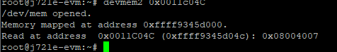
When booted I can look at the pinmux values for the GPIOs we want to use. They seem set to GPIO 0x08214007
However, The pins # seem off by one (GPIO0_18 is on pin 19?)
 cat /sys/kernel/debug/pinctrl/11c000.pinctrl-pinctrl-single/pins
registered pins: 173
pin 0 (PIN0) 0:? 11c000 00040007 pinctrl-single
pin 1 (PIN1) 0:? 11c004 00050004 pinctrl-single
. . .
pin 17 (PIN17) 0:? 11c044 00010004 pinctrl-single
pin 18 (PIN18) 0:? 11c048 08054000 pinctrl-single
pin 19 (PIN19) 0:? 11c04c 08214007 pinctrl-single
pin 20 (PIN20) 0:? 11c050 08214007 pinctrl-single
pin 21 (PIN21) 0:? 11c054 08214007 pinctrl-single
pin 22 (PIN22) 0:? 11c058 00050004 pinctrl-single
pin 23 (PIN23) 0:? 11c05c 00050004 pinctrl-single
pin 24 (PIN24) 0:? 11c060 00050004 pinctrl-single
pin 25 (PIN25) 0:? 11c064 00050004 pinctrl-single
pin 26 (PIN26) 0:? 11c068 00050004 pinctrl-single
pin 27 (PIN27) 0:? 11c06c 08214007 pinctrl-single
pin 28 (PIN28) 0:? 11c070 00050004 pinctrl-single
. . .
pin 53 (PIN53) 0:? 11c0d4 08214007 pinctrl-single
pin 54 (PIN54) 0:? 11c0d8 08214007 pinctrl-single
pin 55 (PIN55) 0:? 11c0dc 00010004 pinctrl-single
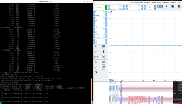
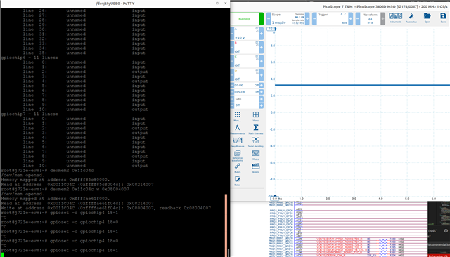
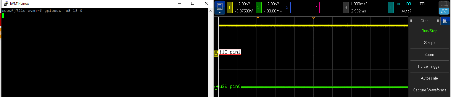
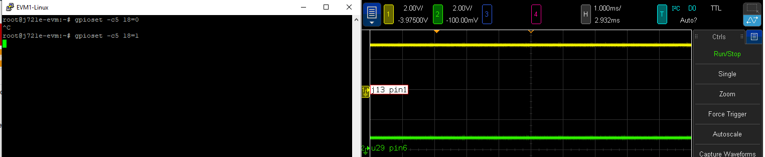
Then if I try to control one of the GPIOs, say GPIO_53, which is normally mapped to SPI3_CS2 and does not go through a selection mux. I don't see it change.
The gpio chips are as follows.
gpiodetect
gpiochip0 [1-0020] (16 lines)
gpiochip1 [1-0022] (24 lines)
gpiochip2 [3-0020] (8 lines)
gpiochip3 [5-0020] (8 lines)
gpiochip4 [42110000.gpio] (84 lines)
gpiochip5 [600000.gpio] (128 lines)
gpiochip6 [601000.gpio] (36 lines)
gpiochip7 [0-0048] (11 lines)
gpiochip8 [0-004c] (11 lines)
gpiochip9 [2-0020] (8 lines)
Chip 5 seems like it matches with main_gpio0 from the device tree (Address 0x600000)
gpioset -c 5 53=1 // Nothing changes on the scope we have connected to GESI Board J5 pin 6
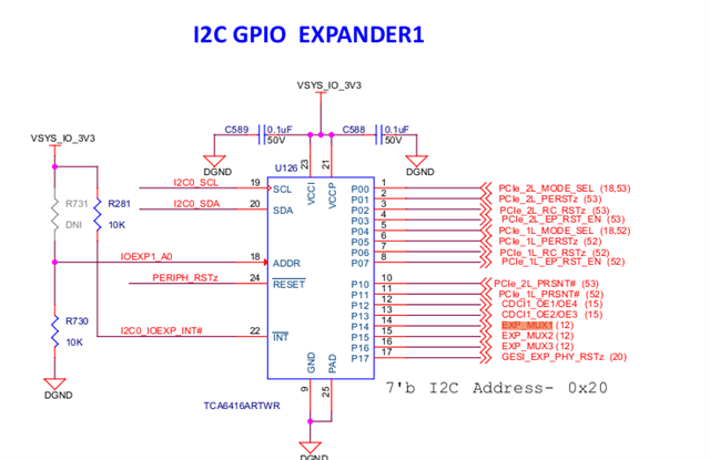
I know some of the GPIOS go through muxes and have to be set with the expander GPIOS on the main board. I have the tried the GPIO_HOG in the device tree as follows by looking at the board(s) schematics.
&exp1 {
   // Enables MCAN4-7 if low rather then PWM signals
	p14-hog {
		/* P15 - EXP_MUX1 */
		gpio-hog;
		gpios = <12 GPIO_ACTIVE_HIGH>;
		output-low;
		line-name = "EXP_MUX1";
	};
   // Enables I2C 5 SDA and SCL on Gesi board if high
	p15-hog {
		/* P15 - EXP_MUX2 */
		gpio-hog;
		gpios = <13 GPIO_ACTIVE_HIGH>;
		output-high;
		line-name = "EXP_MUX2";
	};
   // Enables UART3 and some different MDIO signals when high
	p16-hog {
		/* P16 - EXP_MUX3 */
		gpio-hog;
		gpios = <14 GPIO_ACTIVE_HIGH>;
		output-high;
		line-name = "EXP_MUX3";
	};
};
I still cannot see any of the GPIOS toggle or change values.
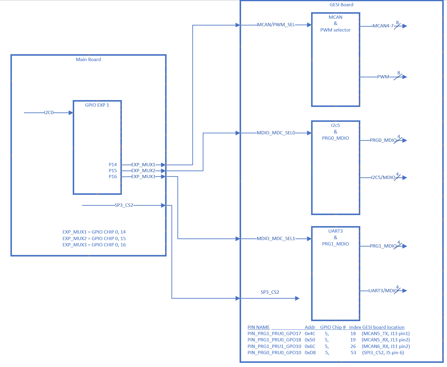
Any help would be appreciated. Below is a diagram showing our understanding of the EVM and the GPIOS we are trying to use.