This thread has been locked.

If you have a related question, please click the "Ask a related question" button in the top right corner. The newly created question will be automatically linked to this question.

AM3352: SYSBOOT issues

Part Number: AM3352

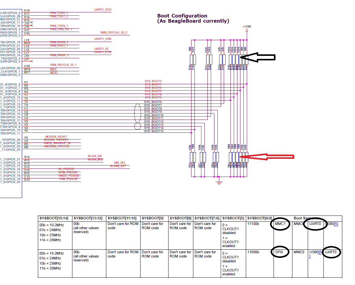
See schematic below with the SYSBOOT configuration.
Below the schematic there are a table showing the two different boot modes we want to switch between during development: Either boot from eMMC (connected to MMC1 bus) or from the SPI NOR Flash.
In the lower schematic below it can be seen how the SPI NOR Flash is connected to SPI0.

  • The default setting of the SYSBOOT is shown in the schematic below (black arrow) which corresponds to the top row of the table below, i.e. MMC1 (our eMMC) is the first tried boot medium.
  • But by moving the pointed out pull-up resistor (black Arrow) on SYSBOOT bit2 to a become a pull-down resistor instaed (red arrow) the boot mode becomes the lower one in the table, i.e. the SPI Nor Flash connected to SPI0 is chosen to be first boot medium. UART0 remains "down the line" so to say. to be the last chance to boot from if not the SPI Flash.

The issue:

  • When SYSBOOT is as in schematic (SYSBOOT[4:0]=11100b, i.e. the top row in the table is valid,  the eMMC isthen a "CCCCC" is output via UART0 as it should be
  • But when SYSBOOT[4:0] is changed to 11000b (SPI Flash instead of eMMC), then no "CCCCC" is output via UART0!, It is totally silent on that line.

--> What is wrong here?

  • Where are the schematics?
  • Hello Biser,

    The schematics were copied in below my text but they seem not to appear in my post, its empty space below my text.

    I try to provide the schematics using "Insert a File" instead in this post.


    Best regards,

    Peter

  • Please check whether your SPI flash is fully compliant to the requirements listed in section 26.1.8.6 of the AM335X TRM Rev. P. Also check the subsections 26.1.8.6.2 and 26.1.8.6.3. What probably happens is the ROM code tries to boot from SPI and reads junk.
  • Thanks for quick response.

    I will check that things out (again), i.e. that the SPI Flash complies with all functional requirements. It seems to do that on all items but: I´m bit unsure of if it complies with the expected sector sizes (512 byte) and addresses mentioned in ch. 26.1.8.6.3. The SPI Flash memory datasheet mentions 64KB sectors with 32KB and 4KB subsectors....? It is a 64MB Flash so it has 0-1023 sectors, each of 64KB size.

    If the Sitara tries to read 0.5KB (512byte) at a time and the smallest Flash memory sectors are 4KB, do we have a problem here? Or does the sectors as the Sitara specifies just describes how large "pieces"/sectors that it scans per read? In this case it would be the first half (4x512byte = 2KB) of the first subsector (4KB) which could be ok, or?

    Then there is the expected values at each sector address; 0x0 or 0xFFFFFFFF. I don´t know how the data in an empty Flash is set. What if the unprogrammed default value of the data bits happens to be 0x0 or 0xFFFFFFF, does the Sitara try to boot then and since SPI0 is the first boot device checked that would explain why we don´t get any "C" at all out from the ROM code (via UART0)?

    A copule of other questions:

    * Shouldn´t the ROM code output "CCCC" via UART0 as usual even if it reads junk from the SPI, i.e. continue with the next potential boot device according to the SYSBOOT settings?

    * I guess that the SPI0 settings in the PinMux are not valid at this early stage? (That´s at least what I understand from the first sentence in ch. 26.1.8.6.2)

    BR,

    Peter

  • I am not sure that this flash will work for booting. We don't have any EVM with this type of flash.

    * Shouldn´t the ROM code output "CCCC" via UART0 as usual even if it reads junk from the SPI, i.e. continue with the next potential boot device according to the SYSBOOT settings?

    There is no specific device identification routine that is executed by the ROM code to identify whether a boot device is preset or not. If no SPI device is present, the sector read will return only 0xFFFFFFFF and the SPI boot will be treated as failed. However if some other value is returned, ROM code will assume that a valid SPI device is present and will proceed with sector read. It will read the first four 512 byte sectors, which should contain the image size. If the value of addresses 0x0, 0x200, 0x400 and 0x600 is neither 0x0 nor 0xFFFFFFFF, then the boot will proceed. Else it will move to the next sector. Only if no image is found after checking four sectors, the ROM bootloader will move to the next device.

    * I guess that the SPI0 settings in the PinMux are not valid at this early stage? (That´s at least what I understand from the first sentence in ch. 26.1.8.6.2)

    The ROM Code initializes the SPI controller, PIN MUXING and clocks for communicating with the SPI device.
  • Dear Biser,

    Regarding the AM3352 support for this type of Micron SPI NOR Flash, see this extraction from a joint Micron - Texas document:


    In our case we use Micron MT25QU512ABB so that should be fine, at least as being a MT25Q device. But what´s worries me a bit is that the table only specifies memory sizes up to 128Mb (16MB). The MT25Q series have memory sizes larger than that. We want to use the 512Mbit version (64MB) of MT25Q. 
    Since the SPI Flash as well as the Sitara both support 24bit address and Read 03h it should be possible for the AM3352 to read out more than just 16MB??
    Or is there really a 16MB limitation by the Sitara after all - and why then, if that´s the case?

    Regarding "CCCCC" I don´t mean that the Sitara should identify the memory or something like that. I refer to the "CCCC" that the ROM code outputs via UART0 when it is searching for a bootable device according to the SYSBOOT setting.

    What could be the reason for that we don't get any "C" at all out when we change the SYSBOOT to make the Sitara to look at SPI0 and not MMC1 (where we have an eMMC Flash)?
    When we have the SYSBOOT setting that includes MMC1 (but not SPI0) then we see "CCCC" coming out from UART0. But not when we change one SYSBOOT pin to make it ignore MMC1 but include SPI0 instead as a possible boot device.

    I hope that these things clarifies things. If not, let me know! We really need to know if can use the SPI NOR Flash we have selected - or not. And if the latter is the case: Why not?.

    Best regards,

    Peter