This thread has been locked.
If you have a related question, please click the "Ask a related question" button in the top right corner. The newly created question will be automatically linked to this question.
Hi Team,
We have designed a board with AM5648 SoC. We are in board bring up stage and have observed a strange issue in few of our boards. Please find the details below:
1. We have set SD card as primary boot source and eMMC as secondary boot source.
2. We are operating eMMC in HS200 Mode. For initial few boards we have tested eMMC with RTOS test application, and have not observed any inconsistency.
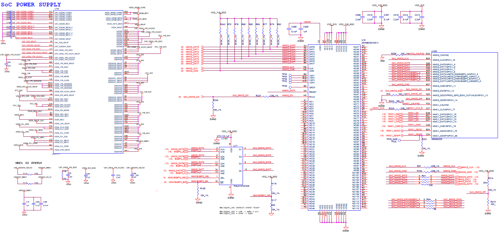
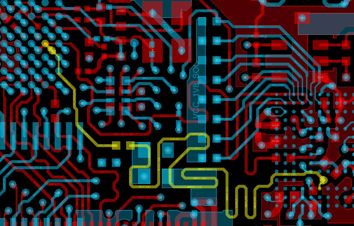
3. However, for next set of boards among the same build, we observed inconsistency with eMMC test. Hence, we replaced the series resistor on clock path from 22E to 33E. After this we observed that it was working fine for few boards. But, few boards failed to boot after this re-work. As we have set MMC1 as primary boot device and MMC0 as secondary boot device, how can a rework on MMC0 is causing the board to fail during boot? Is there anything to do with the series resistor change. Please note that when we again replace the resistor to 22E, the board boots. However, eMMC test will fail.
4. Voltages and clock looks fine and the processor is out of reset all the time. Also note that when we downgrade the clock to 52MHz(SDR50), we are not observing any inconsistency issue with eMMC.
Appreciate your quick reply.
Regards,
Karthik
Your post mentions AM5648. I assume you are asking about AM6548, please confirm.
I would like to understand what software is being used when you observe this issue.
Can you provide PCB trace lengths for each CLK, CMD, and DAT signal for each port? For CLK, provide trace length on each side of the series termination resistor.
It may be helpful if you can provide schematic of MMC connectivity, including power supply connections.
Regards,
Paul
Thank you for the response.
Yes, we are using AM6548 SoC.
Software details: We are using the latest RTOS SDK release, i.e "ti-processor-sdk-rtos-am65xx-evm-05.03.00.07-Linux-x86-Install.bin" version is "05.03.00.07"
We are using eMMC in 4-bit mode (higher 4-bit is multiplexed with EQEP and the MUX is default enabled to EQEP Interface) as shown below.
Please find the attached schematics, length report and screenshot of the clock routed in PCB Layout.
Appreciate your quick response.
Warm Regards,
Navya
Thank you for the response.
Yes, we
peaves said:Your post mentions AM5648. I assume you are asking about AM6548, please confirm.
I would like to understand what software is being used when you observe this issue.
Can you provide PCB trace lengths for each CLK, CMD, and DAT signal for each port? For CLK, provide trace length on each side of the series termination resistor.
It may be helpful if you can provide schematic of MMC connectivity, including power supply connections.
Regards,
Paul
are using AM6548 SoC.peaves said:Your post mentions AM5648. I assume you are asking about AM6548, please confirm.
I would like to understand what software is being used when you observe this issue.
Can you provide PCB trace lengths for each CLK, CMD, and DAT signal for each port? For CLK, provide trace length on each side of the series termination resistor.
It may be helpful if you can provide schematic of MMC connectivity, including power supply connections.
Regards,
Paul
Software details: We are using the latest RTOS SDK release, i.e "ti-processor-sdk-rtos-am65xx-evm-05.03.00.07-Linux-x86-Install.bin" version is "05.03.00.07"
We are using eMMC in 4-bit mode (higher 4-bit is multiplexed with EQEP and the MUX is default enabled to EQEP Interface) as shown below.
Please find the attached schematics, length report and screenshot of the clock routed in PCB Layout.
Appreciate your quick response.
Warm Regards,
Navya
I see a few problems that need to be addressed.
It appears you may have missed a very important note that describes limitations associated with pin multiplexing of the 4 MSB data signals when using the lower LSB for MMC functions. See the following note which is attached to the MMC0 Signal Description Table in the data sheet.
When MMCSD0 or MMCSD1 is used, any non-MMC signal function multiplexed with the respective pins are not available. This is due to the MMC having an internal IO multiplexer which is controlled by MMCSD0/1_SS_PHY_CTRL_1_REG[31] IOMUX_ENABLE. This internal IO multiplexer is primary for the signal functions associated with MMCSD pins, and the PADCONFIG’s MUXMODE is secondary. Additionally, the internal IO multiplexer affects all of the MMCSD0 or MMCSD1 pins, regardless of configured data bus width. Therefore, when MCSD0/1_SS_PHY_CTRL_1_REG[31] IOMUX_ENABLE = 0, the respective MCSD pins are configured for eMMC/SD functionality, regardless of the PADCONFIG [MUXMODE] setting.
You will not be able to utilize any secondary signal function on the MMC0_DAT[7:4] when using MMC0_DAT[3:0] for MMC signal functions since the first level of pin multiplexing has a single global control bit.
You should remove series resistors from all signals except CLK.
The series termination resistor on CLK must be close to the source to be effective. So it needs to be moved over as close as possible to the AM65xx device.
You didn’t provide SD Card connectivity, so cannot comment on any potential issue with this port.
Regards,
Paul