This thread has been locked.

If you have a related question, please click the "Ask a related question" button in the top right corner. The newly created question will be automatically linked to this question.

AM5728: VOUT2 timings

Part Number: AM5728
Other Parts Discussed in Thread: DS90C387A, , CDCVF2505

Our customer wants to connect AM5728 (VOUT2) to DS90C387A (Single-to-dual) with 144MHz PCLK, but it does not seem possible.

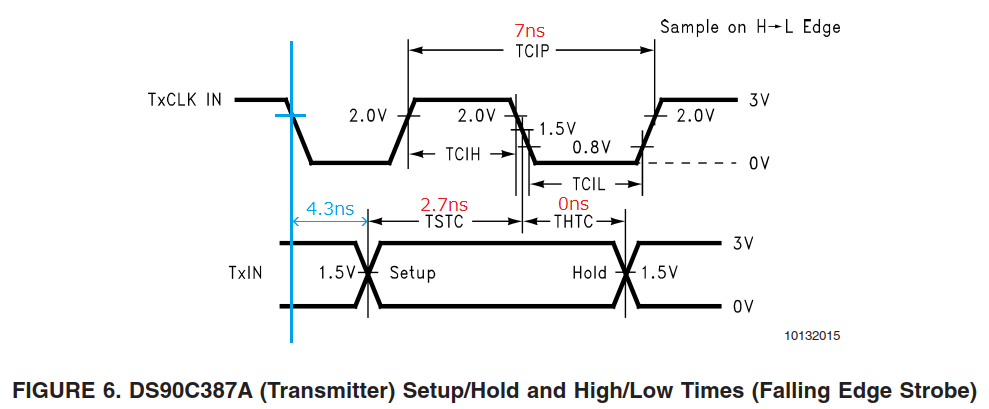
For DS90C387A, the setup time and hold time are as follows.

 - TxIN Setup to TxCLK IN (TSTC): 2.7ns
 - TxIN Hold to TxCLK IN (THTC): 0ns

For AM5728 (VOUT2), the delay time of each Manual IO Timings Modes that supports 144MHz PCLK is as follows.

 - MANUAL1 (Alternate): 1.51ns (MIN) - 4.55ns (MAX)
 - MANUAL3: 2.78ns (MIN) - 5.91ns (MAX)
 - MANUAL4: 3.55ns (MIN) - 6.61ns (MAX)

To meet the setup time of DS90C387A, the maximum delay time must be less than 4.3ns, but AM5728 (VOUT2) does not meet it.

Can you tell me how to connect AM5728 (VOUT2) to DS90C387A with 144MHz PCLK?

Can AM5728 (VOUT2) be customized IO timings?

Best regards,

Daisuke

  • Hi,

    If you use default switching characteristics (Table 7-15 from the AM572x Datasheet SR2.0 Rev. F), the maximum delay time for DPI2 (IOSET2) is 2.5ns.

  • Hi Biser-san,

    Thank you for your reply.

    Daisuke Maeda said:

    Can you tell me how to connect AM5728 (VOUT2) to DS90C387A with 144MHz PCLK?

    The MANUAL2 (Default) Timings mode does not support 144MHz (< 7ns) PCLK because the minimum cycle time for output pixel clock is 11.76ns.

    Best regards,

    Daisuke

  • Daisuke,

    There is sufficient margin at a PCLK of 144MHz to interface these devices.  However, the clock must be delayed to meet the set-up and hold requirements.  You can use the dielectric constant of your PCB material to calculate the signal propagation delay.  You will need to length-match the data and control signals.  Then you can add extra track length to the clock to delay it.  You can use the Alternate Switching Characteristics if you add 1ns of delay to the clock signal.  Assuming standard FR4 PCB material, this will be about 6 inches of copper track added to the clock signal relative to the matched length of the data and control signals.

    Stripline signal propagation delay (in picoseconds per inch) = 84.6*SQRT(Dk)

    For standard FR4 material with a Dk=4, the stripline signal propagation delay is 170ps/in

    Microstrip routes are faster and have a signal propagation delay = 84.6*SQRT(0.475*Dk+0.67)

    For standard FR4 material with a Dk=4, the microstrip signal propagation delay is 135ps/in

    You may also need to account for signal propagation delay through vias if the number of vias per route vary or the via barrel length varies significantly.  Most PCB layout packages can calculate accurate signal propagation delays to simplify this process.

    Another solution is implementation of a zero-delay clock buffer.  Many of these buffers have configurable delay options that can be controlled by selection of a load capacitor.

    Tom

  • Hi Tom-san,

    Thank you for your reply.

    Tom Johnson 16214 said:

    Another solution is implementation of a zero-delay clock buffer.  Many of these buffers have configurable delay options that can be controlled by selection of a load capacitor.

    Could you tell me the recommended devices in the clock buffers?

    The calculation results of the time range of propagation delay of PCLK for connecting AM572x (VOUT2) to DS90C387A is as follows:

      - Fpr MANUAL1 (Alternate): 0.31ns (Min) - 1.51ns (Max)
      - For MANUAL3: 1.67ns (Min) - 2.78ns (Max)
      - For MANUAL4: 2.37ns (Min) - 3.55ns (Max)

    The spreadsheet used to calculate these results is attached here: Delay time for connecting AM572x (VOUT2) to DS90C387A.xlsx

    I can't find a device that matches any of these results.

    Best regards,

    Daisuke

  • Daisuke,

    An example is the CDCVF2505.  You can add capacitance to the CLKOUT pin to shift the other outputs relative to the input.  See Figure 10 and the related text in the datasheet for more details.  The full selection of zero-delay clocks can be found at http://www.ti.com/clock-and-timing/buffers/zero-delay-buffers/products.html.

    Tom

  • Hi Tom-san,

    Thank you for your reply.

    I will suggest to our customer a case of using a zero delay buffer, but it is very difficult to control the clock delay by PCB trace and load capacitance.

    Could you tell me if there is any use case that uses AM572x DPI Video Output and other devices to display a high resolution of 1080p or higher?

    Best regards,

    Daisuke

  • Daisuke,

    I believe that it can do 1080p60 and possibly higher resolutions.  However, that is not my expertise.  You should post that question separately so that you can get it answered by the proper experts.

    Tom

  • Hi Tom-san,

    Thank you for your reply.

    I suppose that there is no use case that uses AM572x DPI Video Output to display a high resolution of 1080p60 or higher.

    Jacinto 6 expert working in the same office as me does not know a use case that exceeds 720p60.

    Best regards,

    Daisuke

  • Hi,

    My new thread is here: http://e2e.ti.com/support/processors/f/791/t/848318

    Best regards,

    Daisuke