This thread has been locked.

If you have a related question, please click the "Ask a related question" button in the top right corner. The newly created question will be automatically linked to this question.

AM5728: custom board based on EVM572X do not boot

Part Number: AM5728
Other Parts Discussed in Thread: TMDSEVM572X, , BEAGLEBOARD-X15

I create a new thread because the original one have been locked : https://e2e.ti.com/support/processors/f/791/p/887508/3282263 (I didn't have access on material because of lockdown)

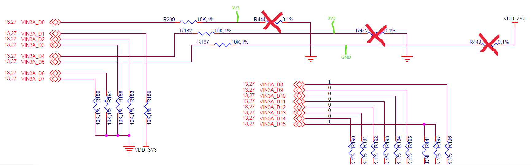
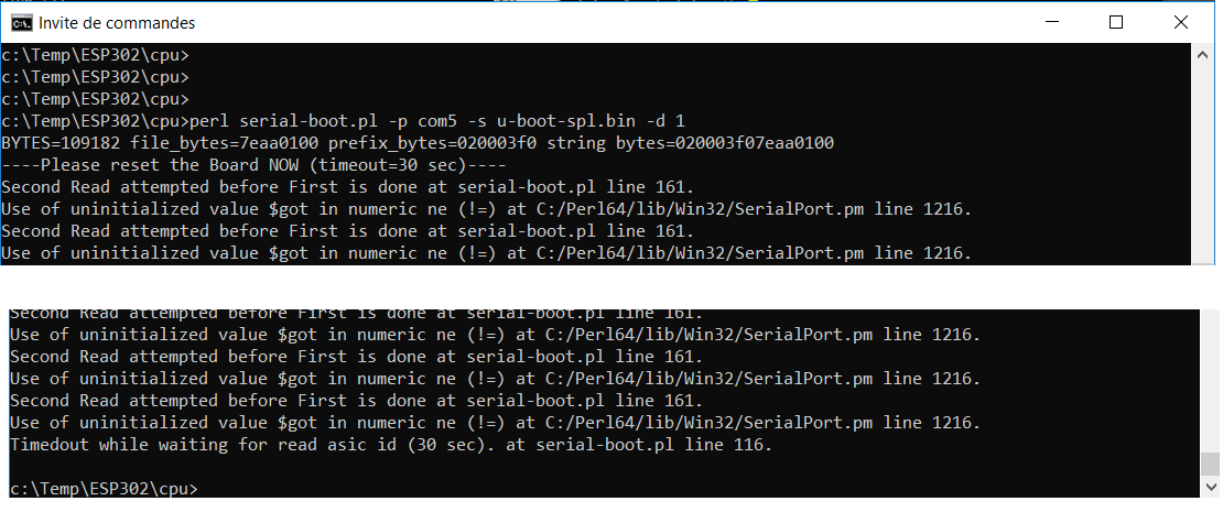
I have tried to put jumper in UART boot mode, and I have nothing on serial console (on P10 connector, 115200 baudrate)

  • Hi Chrisophe,

    Thanks for starting a new thread and providing a reference of the older one.

    We will be able to provide you some feedback early next week, this week I do not have access to the board. 

    Regards

    Karthik

  • Hi Christophe,

    Please refer the pdf for UART boot:
    e2e.ti.com/.../AM57_5F00_UART_5F00_Boot_5F00_SOP_5F00_By_5F00_TI_5F00_Rio_5F00_Final.pdf

    latest e2e query where we have UART boot working on am5728-evm:


    Hope you can try out the UART boot.

    BR,
    Keerthy

  • Unfortunatly I cannot change the jumpers J2-4-6 on my beagleboard because their are hardwired.

    On my custom board jumper have been removed and replaced by resistors. I modified my board with wires to have the good boot configuration :

    But it doesnt work... (I see nothing on UART console)

    I have ordered a TMDSEVM572X kit to be sure that I follow the good procedure. With the TMDSEVM572X I see random characters on UART, it seems to works, but I don't know where to find the serial-boot.pl script to send binary files.

  • good news !

    I just redid the jumper wire modification on a new custom board and it works : I have random caracters on UART console.

    I think I broken something on the other board...

    Now the only thing I miss to test the UART boot mode on my custom board is the serial-boot.pl script.

  • Christophe,

    https://e2e.ti.com/support/processors/f/791/t/534961

    Open the query there is zip folder which should be containing the serial-boot.pl.

    Best Regards,
    Keerthy

  • After some issues to install SerialPort on ActivePerl 5 I finally managed to launch the script, but it end in a timeout after less than 1 second (even if the log say I have 30sec to reset the board...)

  • Hi Christophe,

    UART boot working on the latest SDK: https://e2e.ti.com/support/processors/f/791/t/920527

    The above thread contains all the references. Windows with perl combination is working well
    on am5728 UART boot.

    Regards,
    Keerthy

  • Hi

    the perl script is now working with strawberryperl 32bits.

    The script ends with "u-boot-spl.bin file download completed", then I connect to the serial port with teraterm but I don't see the CCC characters and the YMODEM send doesn't work

    I am not sure if I am using the good spl file, where is it located in the SDK ?

    Regards,

    Christophe

  • Hi Christophe,

    It is under board-support/prebuilt-images/

    MLO-am57xx-evm ==>  MLO & u-boot-am57xx-evm.img ==> u-boot.img

    Also u-boot-spl.bin is present as u-boot-spl-.bin-am57xx-evm

    Regards,
    Keerthy

  • Thanks the u-boot load is now working !

    But I am facing a new issue : 

    How do i send the kernel file through UART ?

    And what I have to do with MLO file ?

    For now I sent u-boot-spl.bin through perl, and u-boot.img through YMODEM

    UART will be very slow to send a kernel file and rootfs... Perhaps can I go through NFS kernel and filesystem now I have a working u-boot ?

  • I just tried the same procedure on my custom board and it is not working...

    the SPL file transfer through perl script is working, but I dont have the CCC output en UART as I have on the EVM board

  • Hello Christophe,

    That is really good to hear! Yes now you can try tftp/nfs to get to kernel prompt.

    - Keerthy

  • Any idea about why I dont have the CCC on my custom board ?

    SPL doesnt seem to be executed, or perhaps it doesnt output on the good uart...

    I think this could be the same issue that make the SD boot not working on my custom board

  • Christophe,

    This would be the time to check the differences between your board and evm since we
    have working condition on evm and not working on custom board. What is different on your
    custom board?

    - Keerthy

  • We have removed interfaces we do not need :

    -        3×SuperSpeed USB 3.0 host

    -        HighSpeed USB 2.0 client

    -        eSATA

    -        full-size HDMI video output

    -        Stereo audio in and out

    We changed the obsolete SD card connector by a new one

    We added a CR2032 battery cell holder for the RTC clock

    We replaced obsolete eMMC by an equivalent : ISSI  IS21ES04G-JCLI 

    We replaced some others obsolete component by equivalent

    I can share the BOM and schematic if needed

    And the routing of the PCB is different.

  • Christophe,

    Can you look at the pinmux configuration here in the u-boot source directory:

    board/ti/am57xx/mux_data.h

    Check if your uart2 mux are set right:

    {UART2_RXD, (M14 | PIN_INPUT_PULLDOWN)}, /* uart2_rxd.gpio7_26 */
    {UART2_TXD, (M14 | PIN_INPUT_PULLDOWN)}, /* uart2_txd.gpio7_27 */
    {UART2_CTSN, (M2 | PIN_INPUT_PULLUP)}, /* uart2_ctsn.uart3_rxd */
    {UART2_RTSN, (M1 | PIN_OUTPUT)}, /* uart2_rtsn.uart3_txd */

    - Keerthy

  • Keerthy,

    I have the same as you in my mux_data.h from SDK 06.03

    But on my schematic I have debug on UART3, as in EVM schematic

    And I use the same u-boot on the two boards


    Regards,

    Christophe

  • Hi Christophe,

    It seems we are pretty much done comparing software. Do you want the hardware team to look at
    your schematics? We have the exact same u-boot booting on evm and not coming up on custom board.

    - Keerthy

  • Hi Keerthy,

    Yes if you can get hardware team involved it could help. How do I share my schematics ?

    Thanks you very much for your help.

    Christophe

  • I can help with some hardware questions. To summarize, you are attempting to download binary using UART boot on a customer hardware.  The download seems to happen, but then you get no response on the terminal (which is expected once binary is executed)?  You've testing your setup using a TI EVM - and it works correctly.  Therefore - you believe the setup is correct, and the issue is with the custom board.  Is my understanding correct?

    Have you verified the device comes out of reset (and stays out of reset)?  Can verify RSTOUTn goes high after power-up.

    What are ALL the SYSBOOT settings?  If you have a debugger/JTAG connection - there is a register which shows the latched SYSBOOT values

    What is your clock input on OSC0?  Is it same frequency as TI EVM?

    What are your UART connections for booting and terminal?  Do these match the TI EVM? 

  • I can help with some hardware questions. To summarize, you are attempting to download binary using UART boot on a customer hardware.  The download seems to happen, but then you get no response on the terminal (which is expected once binary is executed)?  You've testing your setup using a TI EVM - and it works correctly.  Therefore - you believe the setup is correct, and the issue is with the custom board.  Is my understanding correct?

    => yes correct

    Have you verified the device comes out of reset (and stays out of reset)?  Can verify RSTOUTn goes high after power-up.

    => yes RSTOUTn is high after power up, and still high after spl load

    What are ALL the SYSBOOT settings?  If you have a debugger/JTAG connection - there is a register which shows the latched SYSBOOT values

    => I tried but I have a problem with wt JTAG connection (Blackhawk USB560v2 System trace) :

    -----[Perform the Integrity scan-test on the JTAG DR]------------------------

    This test will use blocks of 64 32-bit words.
    This test will be applied just once.

    Do a test using 0xFFFFFFFF.
    Test 1 Word 0: scanned out 0xFFFFFFFF and scanned in 0x2B99002F.
    Scan tests: 1, skipped: 0, failed: 1
    Do a test using 0x00000000.
    Test 2 Word 0: scanned out 0x00000000 and scanned in 0xFFFFFFFF.
    Scan tests: 2, skipped: 0, failed: 2
    Do a test using 0xFE03E0E2.
    Test 3 Word 0: scanned out 0xFE03E0E2 and scanned in 0x00000000.
    Scan tests: 3, skipped: 0, failed: 3
    Do a test using 0x01FC1F1D.
    Test 4 Word 0: scanned out 0x01FC1F1D and scanned in 0xFE03E0E2.
    Scan tests: 4, skipped: 0, failed: 4
    Do a test using 0x5533CCAA.
    Test 5 Word 0: scanned out 0x5533CCAA and scanned in 0x01FC1F1D.
    Scan tests: 5, skipped: 0, failed: 5
    Do a test using 0xAACC3355.
    Test 6 Word 0: scanned out 0xAACC3355 and scanned in 0x5533CCAA.
    Scan tests: 6, skipped: 0, failed: 6
    Some of the values were corrupted - 1.6 percent.

    The JTAG DR Integrity scan-test has failed.

    [End: Blackhawk XDS560v2-USB System Trace Emulator]

    What is your clock input on OSC0?  Is it same frequency as TI EVM?

    => I dont have access to an oscilloscope today, I will measure the frequency asap.

    What are your UART connections for booting and terminal?  Do these match the TI EVM? 

    => I use the same UART settings for both boards

  • Please provide your SYSBOOT settings.  Are the SYSBOOT pins shared with other functions/peripherals - or are they dedicated to only SYSBOOT settings?

    Regarding the JTAG - have you tried reducing the clock rate (in the configuration settings)?

    Have you verified all the processor power rails are at the correct voltage (using voltmeter)?  You need to check every rail.

  • Hi,

    My sysboot configuration is as below :

      original board modified board (to boot on uart)
    SYSBOOT0 0 1
    SYSBOOT1 1 1
    SYSBOOT2 0 0
    SYSBOOT3 0 0
    SYSBOOT4 0 1
    SYSBOOT5 1 0
    SYSBOOT6 0 0
    SYSBOOT7 0 0
    SYSBOOT8 1 1
    SYSBOOT9 0 0
    SYSBOOT10 0 0
    SYSBOOT11 0 0
    SYSBOOT12 0 0
    SYSBOOT13 0 0
    SYSBOOT14 0 0
    SYSBOOT15 1 1

    SYSBOOT pins are not shared

    The voltages measured on my supply rails are :

    VDD_3V3 : 3.24 V

    VUSB_3V3 : 3.30 V

    LDO_VRTC : 1.80 V

    VDD_SD : 3.28 V

    VDD_SHV5 : 3.28 V

    VDDA_1V8_PHYB : 1.78 V

    VDDA_1V8_PHYA : 1.80 V

    VDDA_1V8_PLL : 1.785 V

    VDD_RTC : 1.05 V

    VDD_MPU : 1.152 V

    VDD_DDR : 1.351 V

    VDD_DSP : 1.062 V

    VDD_CORE : 1.15 V

    VDD_1V8 : 1.80 V

    For the JTAG I have tried with "automatic with faster 35MHz limit" and "automatic with legacy 10.368 MHz limit".

    I have the same issue on my custom board and on the EVM.

  • The JTAG connection is working on EVM without the UART boot mode.

    As my SYSBOOT is hardwired on my custom board I have to test on a new board not modified for UART boot mode, I will tell you the result when it is done.

  • I finally succeed to make the JTAG work in uart boot mode, i have to send spl first...

    CTRL_CORE_BOOTSTRAP register dont have the same value on the 2 boards.

    EVM : 0x00008113

    CUSTOM : 0x00000113

  • my SYSBOOT15 pin was not at the good level, I changed it to have a pull up on it and I have CTRL_CORE_BOOTSTRAP=0x00008113 on my board like in EVM

    UART boot is still not working...

    I will try on a not modified board with the correct SYSBOOT15, perhaps it can makes SD boot to work...

  • Can you provide some feedback on why SYSBOOT15 was not at a good IO level?  According to your previous feedback, these pins are not shared with other functions.  Giving feedback on issue with SYSBOOT15 might point us to other issues.

  • It was an error in my BOM, R441 was mounted instead of R197

  • I found why we have this difference and our BOM. We started from beagleboard-X15 schematic that changed the sysboot15 config :

    As the beagleboard is working I don't think the issue is due to this...

  • Hi,

    I tested one of my custom board in SD boot mode with the sysboot15 correction it doesnt change anything.

    I also measured OSC0 frequency it is the same as EVM : 20MHz

  • Can you send me your schematics?

  • Looking at the SD card cage differences, its a bit confusing.  I think the original SD card cage from BeagleBone pulls the CD signal low when card is inserted.  However - the drawing for the new card cage seems to indicate the reverse - the switch is open when card is inserted.  Can you confirm?

    Also - for UART - are you using FTDI USB adapter for mating with connector P10?  Is orientation correct?

  • Robert Eschler said:

    Looking at the SD card cage differences, its a bit confusing.  I think the original SD card cage from BeagleBone pulls the CD signal low when card is inserted.  However - the drawing for the new card cage seems to indicate the reverse - the switch is open when card is inserted.  Can you confirm?

    Yes you are right, but I already tested to force the CD signal to GND with a wire and it didn't worked

    Robert Eschler said:

    Also - for UART - are you using FTDI USB adapter for mating with connector P10?  Is orientation correct?

    Yes I use the the FTDI USB adapter. I know it is working because I am able to launch a hello world program from JTAG on my custom board and I see the output on UART.

  • Ok.  Good you are able to download a simple code and run.  Which boot mode are you configured for right now (UART or SD)?

    If you are configured for UART - after downloading code, can you connect with JTAG and verify if SDRAM is stable?

    If you are configured for SD card boot - do you have access to a scope?  Do you see any activity on the SD_CLK and SD_CMD signals?

  • I am in SD boot mode. After pressing the reset button I can see activity on SD cmd and clock signals during 170ms :

    After that I am able to connect with JTAG.

    I have successfully launched a helloworld and some diag programs from pdk

    - mem  : OK

    - mmcsd : OK

    - emmc : OK

    - eeprom : OK

    - pmic : OK

    - uart : OK

    All seems to work when I launch from JTAG

  • Keerthy,

    Can we re-visit the software checks now?  It seems the hardware is working as expected.  Can the user download via JTAG to test the software image - and verify it runs?  If not - after attempting to boot - can the user connect with JTAG and verify where the issue occurred (program counter or something)?

    Robert

  • Thanks for your help Robert.

    Keerthy,

    I have already tried to run U-boot through JTAG but I didn't succeed to do it, both on my board and on the EVM.

    I am not able to make my JTAG probe to work on my linux virtual machine, so I need to have a U-boot CCS project on Windows environment.

    Regards,

    Christophe

  • I will be in vacation until september. Please do not close my topic.