Part Number: TDA4VM
Hi,
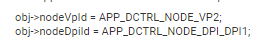
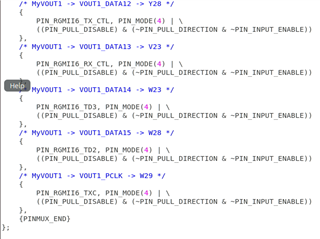
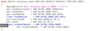
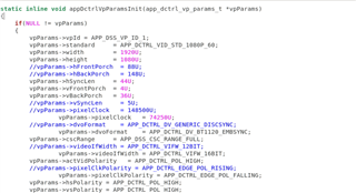
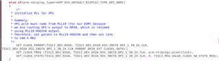
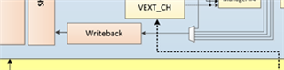
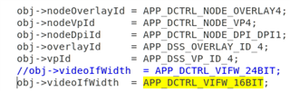
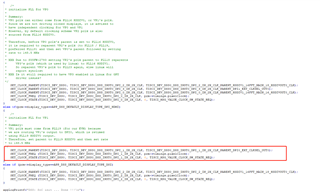
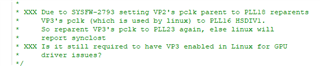
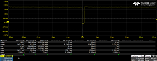
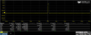
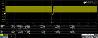
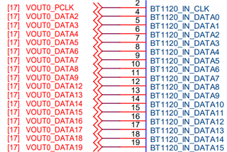
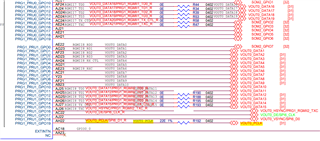
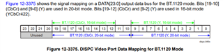
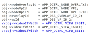
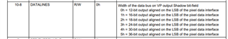
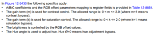
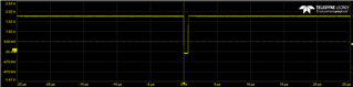
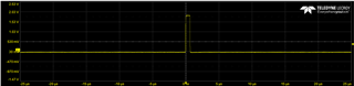
I have set HDMI to Vout1 / DP1 according to the following link, but the clock(pclk) is always about 600 MHz, How to modify it(148.5MHz)?
Looking forward to your reply, thanks a lot!
Original question:

Part Number: TDA4VM
Hi,
I have set HDMI to Vout1 / DP1 according to the following link, but the clock(pclk) is always about 600 MHz, How to modify it(148.5MHz)?
Looking forward to your reply, thanks a lot!