A related question is a question created from another question. When the related question is created, it will be automatically linked to the original question.
If you have a related question, please click the "Ask a related question" button in the top right corner. The newly created question will be automatically linked to this question.
When a portion of the ADC is used, any unused AIN ball must be pulled to VSS through a resistor or direct connection.
If the entire ADC is not used, each of the following balls must be connected directly to VSS. VDDA_ADC ADC0_AIN0 ADC0_AIN1 ADC0_AIN2 ADC0_AIN3 ADC0_AIN4 ADC0_AIN5 ADC0_AIN6 ADC0_AIN7
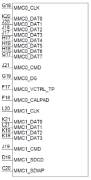
MMC
I will need to research the answer for MMC0.
The pins associated with MMC1 can be multiplexed to many signal functions including GPIO. Therefore, it seems unlikely these pins would not used. We expect these pins to be treated the same as standard LVCMOS IOs.
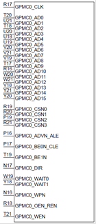
GPMC
You must use the GPMC0_AD[15:0] pins of GPMC to configure the AM64x boot mode. The other pins can be multiplexed to many signal functions including GPIO. Therefore, it seems unlikely these pins would not used. We expect these pins to be treated the same as standard LVCMOS IOs.
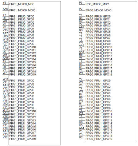
PRGx_MDIOx
The pins associated with PRGx_MDIOx can be multiplexed to many signal functions including GPIO. Therefore, it seems unlikely these pins would not used. We expect these pins to be treated the same as standard LVCMOS IOs.
The default state of most standard LVCMOS IOs turns off the input buffer, turns off, the output buffer, and turns off the internal pulls. Pins associated with these IOs can be left unconnected if not used. You should review the default state of each pin shown in the Pin Attributes table of the datasheet and confirm your usage of the pin is compliant to operating conditions defined in the datasheet of all attached devices.
I confirmed the recommended connectivity for MMC0 when not used.
VDD_MMC0 and VDD_DLL_MMC0 should be connected to the same power source as VDD_CORE. VDDS_MMC0 can be connected to any 1.8V power source that does not violate our recommended power sequence. MMC0_CALPAD, MMC0_CLK, MMC0_CMD, MMC0_DS, and MMC0_DAT[7:0], should be left unconnected.