This thread has been locked.

If you have a related question, please click the "Ask a related question" button in the top right corner. The newly created question will be automatically linked to this question.

PROCESSOR-SDK-OMAPL137: Getting started

Part Number: PROCESSOR-SDK-OMAPL137
Other Parts Discussed in Thread: OMAP-L137

Hello everyone,

I have OMAP-L137 EVM. I want to work in this kit with ccs version 6 or 7.

1)Kindly share the examples and all the requirements which I need to work in this board.

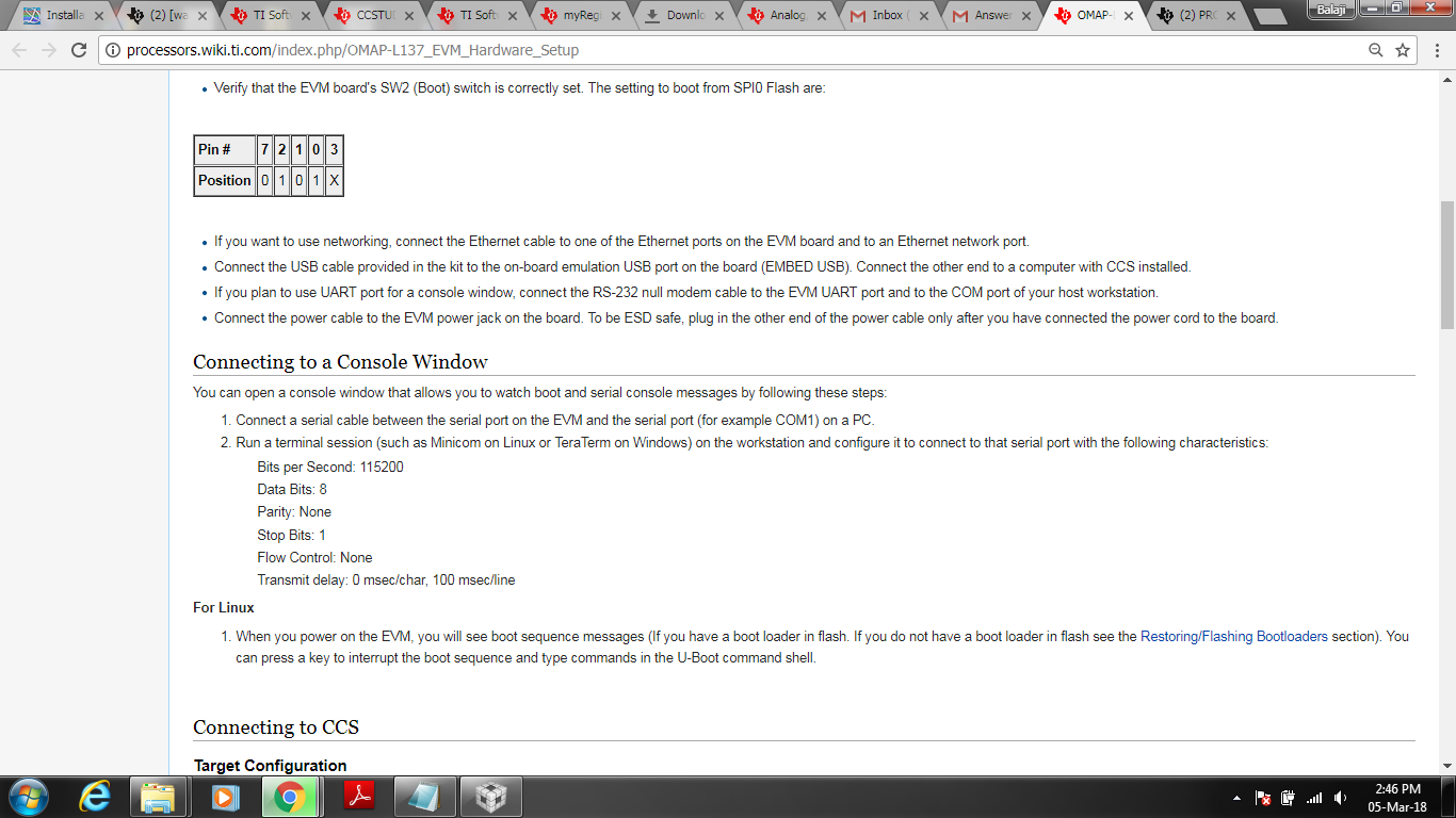
2)Secondly how to connect this board with the pc/laptop? because I got one mini usb cable and one micro usb cable. So which one should I connect to the pc/laptop?

  • Hi Abhishek,

    I suggest you to start with the Processor SDK RTOS Getting started guide at:
    processors.wiki.ti.com/.../Processor_SDK_RTOS_Getting_Started_Guide
    and continue with Processor SDK RTOS Software Developer Guide where you can find examples:
    processors.wiki.ti.com/.../Processor_SDK_RTOS_Software_Developer_Guide
    Check the OMAP-L137 EVM Hardware setup guide about how to connect the board to your PC:
    processors.wiki.ti.com/.../OMAP-L137_EVM_Hardware_Setup

    BR
    Tsvetolin Shulev
  • When I had connected my board to laptop it is not detected because I am using Windows 10, but when connected it to a laptop which has Windows 7 the board got detected?

    Can I have any solution sir.....

  • Seems that the issue is related to Windoes 10 PC's com port settings or driver. You should investigate in this direction.

    BR
    Tsvetolin Shulev
  • Now I am working with windows 7.

    1)The board is detected in device manager by the name "Spectrum Digital xds510 usb" but when I loaded the code  I got an error which is mentioned below

    2)How can I only work with dsp core 6747 and disable ARM9 core.

    3)At the time of adding target configuration I got  two options in the Board or Device window i.e. "EVMOMAPL137" and "OMAPL137", I tried with both but  I got the following result

  • Sorry for the earlier post by mistake it has been published.

    Now I am working with windows 7.

    1)The board is detected in device manager by the name "Spectrum Digital xds510 usb" but when I loaded the code  I got an error which is shown

    2)How can I only work with dsp core 6747 and disable ARM9 core.

    3)At the time of adding target configuration I got  two options in the Board or Device window i.e. "EVMOMAPL137" and "OMAPL137", I tried with both but  I got the following result 

    and I attached the code below

    gpioSample_io.c
    /*
     * gpioSample_io.c
     *
    * This file contains the test / demo code to demonstrate the GPIO driver funct-
     * ionality on DSP/BIOS 5.
     *
     * Copyright (C) 2009 Texas Instruments Incorporated - http://www.ti.com/
     *
     *
     *  Redistribution and use in source and binary forms, with or without
     *  modification, are permitted provided that the following conditions
     *  are met:
     *
     *    Redistributions of source code must retain the above copyright
     *    notice, this list of conditions and the following disclaimer.
     *
     *    Redistributions in binary form must reproduce the above copyright
     *    notice, this list of conditions and the following disclaimer in the
     *    documentation and/or other materials provided with the
     *    distribution.
     *
     *    Neither the name of Texas Instruments Incorporated nor the names of
     *    its contributors may be used to endorse or promote products derived
     *    from this software without specific prior written permission.
     *
     *  THIS SOFTWARE IS PROVIDED BY THE COPYRIGHT HOLDERS AND CONTRIBUTORS
     *  "AS IS" AND ANY EXPRESS OR IMPLIED WARRANTIES, INCLUDING, BUT NOT
     *  LIMITED TO, THE IMPLIED WARRANTIES OF MERCHANTABILITY AND FITNESS FOR
     *  A PARTICULAR PURPOSE ARE DISCLAIMED. IN NO EVENT SHALL THE COPYRIGHT
     *  OWNER OR CONTRIBUTORS BE LIABLE FOR ANY DIRECT, INDIRECT, INCIDENTAL,
     *  SPECIAL, EXEMPLARY, OR CONSEQUENTIAL DAMAGES (INCLUDING, BUT NOT
     *  LIMITED TO, PROCUREMENT OF SUBSTITUTE GOODS OR SERVICES; LOSS OF USE,
     *  DATA, OR PROFITS; OR BUSINESS INTERRUPTION) HOWEVER CAUSED AND ON ANY
     *  THEORY OF LIABILITY, WHETHER IN CONTRACT, STRICT LIABILITY, OR TORT
     *  (INCLUDING NEGLIGENCE OR OTHERWISE) ARISING IN ANY WAY OUT OF THE USE
     *  OF THIS SOFTWARE, EVEN IF ADVISED OF THE POSSIBILITY OF SUCH DAMAGE.
     *
    */
    
    
    /** ============================================================================
     *   @brief A simple example to demonstrate CSL 3.x GPIO register layer usage
         and interrupts in a BIOS application.
     *
     *   @file  gpioSample_io.c
     *
     *   <b> Example Description </b>
     *   @verbatim
     *   This example demonstrates the use of GPIO driver/module. The sample does
     *   this by taking input on GPIO pin GPIO0_8(configured as input pin), via user
     *   switch SW3-1. This GPIO pin is configured to trigger an interrupt at the
     *   rising edge. The ISR handler for this interrupt, GPIO_input_isr is called,
     *   which sets the status variable to 1. Due to this the while loop in the task
     *   breaks and blinks led DS1 which is connected to the GPIO0_12
     *   (configured as output pin).
     *   @endverbatim
     *
     *
     *   <b> Procedure to run the example </b>
     *   @verbatim
     *   1. Open gpioSample project in CCS
     *   2. Build the project
     *   3. Connect to target and load the gpioSample.x674
     *   4. Run the program
     *   5. On the console message "Waiting for user to configure SW3-1" is printed
     *      in a loop
     *      a. This message occurs until the user intervenes for generating interrupt
     *   6. Toggle the user swith SW3-1
     *   8. "GPIO Interrupt occured !" message is printed on the console
     *       a. the movement of switch position causes the GPIO interrupt
     *   9. The User LED DS1 now starts blinking (turning on and off at very low freq)
     *  10. This is the end of demonstration
     *   @endverbatim
     *
     * ============================================================================
     **/
    
    #include "std.h"
    #include "iom.h"
             
    #include "log.h"
    #include "tsk.h"
             
    #include "ti/pspiom/cslr/cslr_gpio.h"
    #include "ti/pspiom/cslr/cslr_syscfg_OMAPL137.h"
    #include "ti/pspiom/cslr/soc_OMAPL137.h"
    #include "ti/pspiom/gpio/Gpio.h"
    #include "ti/pspiom/platforms/evmOMAPL137/gpio_evmInit.h"
    
    extern Gpio_Handle gpio0;
    extern LOG_Obj trace;
    volatile Int32 flag = 0;
    
    #define LOW 0x0
    #define HIGH 0x1
    #define GPIO_BANK_0 0x00
    
    #define GPIO0_8_PIN 9
    #define GPIO0_12_PIN 13
    
    Void GPIO_input_isr(Ptr);
    
    
    Void delay(Void)
    {
        volatile Int32 i,j;
          for(i=0; i<5000; i++)
          {
              for(j=0; j<1000; j++)
              {
                  ;
              }
          }
    }
    
    Void gpioExampleTask(Void)
    {
        Gpio_PinCmdArg UserPinCmdArg;
        Gpio_IntrCmdArg UserIntrCmdArg;
        volatile Int32 ledBlinkCount=4;
    
        /* Call the EVM specific initialization function                          */
        configureGpio();
    
        /* Configure GPIO0_12 as an output */
        UserPinCmdArg.pin = GPIO0_12_PIN;
        UserPinCmdArg.value = Gpio_Direction_Output;
        Gpio_setPinDir(gpio0,&UserPinCmdArg);
    
        /* Configure GPIO(GPIO0_8_PIN) as an input */
        UserPinCmdArg.pin = GPIO0_8_PIN;
        UserPinCmdArg.value = Gpio_Direction_Input;
        Gpio_setPinDir(gpio0,&UserPinCmdArg);
    
    
        /* Set Data high in SET_DATA register for GPIO(GPIO0_12_PIN).            *
         * This turns the LED off -see schematic                                 */
        UserPinCmdArg.pin = GPIO0_12_PIN;
        UserPinCmdArg.value = HIGH;
        Gpio_setPinVal(gpio0,&UserPinCmdArg);
    
        /* Enable GPIO Bank interrupt for bank GPIO_BANK_0                        */
        Gpio_bankInterruptEnable(gpio0,GPIO_BANK_0);
    
        /* Configure GPIO(GPIO0_8_PIN) to generate interrupt on rising edge       */
        Gpio_setRisingEdgeTrigger(gpio0,GPIO0_8_PIN);
    
        /* Set the interrupt handler for GPIO0_8_PIN. However we cannot register
         * interrupts for individual pins in OMAPL137, therefore  register interrupt
         * for the associated bank(BANK0) as a whole
         */
        UserIntrCmdArg.value = GPIO_BANK_0;
        UserIntrCmdArg.bankOrPin = Gpio_BankOrPin_isBank;
        UserIntrCmdArg.isrHandler = (Gpio_Isr)&GPIO_input_isr;
        Gpio_regIntHandler(gpio0,&UserIntrCmdArg);
    
        LOG_printf(&trace, "Waiting for GPIO Interrupt\n");
        while( 0 == flag)
        {
            TSK_sleep(2000);
            LOG_printf(&trace, "Waiting for user to toggle SW3-1\n");
        }
    
        LOG_printf(&trace, "GPIO Interrupt occured !\n");
    
        while(ledBlinkCount > 0)
        {
            /* Make the GPIO pin conected to the LED to low. *
             * This turns on the LED - see schematic         */
            UserPinCmdArg.pin = GPIO0_12_PIN;
            UserPinCmdArg.value = LOW;
            Gpio_setPinVal(gpio0,&UserPinCmdArg);
    
            delay();
    
            /* Make the GPIO pin conected to the LED to high *
             * This turns the off the LED - see schematic    */
            UserPinCmdArg.pin = GPIO0_12_PIN;
            UserPinCmdArg.value = HIGH;
            Gpio_setPinVal(gpio0,&UserPinCmdArg);
    
            delay();
    
            ledBlinkCount--;
    
        }
    
        /* close the GPIO driver handle */
        Gpio_close(gpio0);
    
        LOG_printf(&trace, "End of GPIO sample application!\n");
    }
    
    
    Void GPIO_input_isr(Ptr ignore)
    {
        Gpio_PinCmdArg UserPinCmdArg;
        
        /* To avoid compiler warnings                                             */
        ignore = ignore; 
           
        /* 
        There is significant signal bounce at the GPIO pin connected to the User 
        Switches (SW3). These bounces can generate spurious interrupts (at either
        falling or rising). Hence check the steady state (after some delay).
        However, in real applications this delay-check may be done outside ISR
        */
        delay();
        
        UserPinCmdArg.pin = GPIO0_8_PIN;
        Gpio_getPinVal(gpio0,&UserPinCmdArg);
    
        /* Let this be here now. I want to see the Heart beat :-)                 */
        /* Want interrupts only at rising edge - Check pin in steady state high   */
        if(1u == UserPinCmdArg.value)
        {
            flag=1;
        }
    }
    
    
    gpioSample_main.c
    /*
     * gpioSample_main.c
     *
    * This file contains the test / demo code to demonstrate the GPIO driver funct-
     * ionality on DSP/BIOS 5.
     *
     * Copyright (C) 2009 Texas Instruments Incorporated - http://www.ti.com/
     *
     *
     *  Redistribution and use in source and binary forms, with or without
     *  modification, are permitted provided that the following conditions
     *  are met:
     *
     *    Redistributions of source code must retain the above copyright
     *    notice, this list of conditions and the following disclaimer.
     *
     *    Redistributions in binary form must reproduce the above copyright
     *    notice, this list of conditions and the following disclaimer in the
     *    documentation and/or other materials provided with the
     *    distribution.
     *
     *    Neither the name of Texas Instruments Incorporated nor the names of
     *    its contributors may be used to endorse or promote products derived
     *    from this software without specific prior written permission.
     *
     *  THIS SOFTWARE IS PROVIDED BY THE COPYRIGHT HOLDERS AND CONTRIBUTORS
     *  "AS IS" AND ANY EXPRESS OR IMPLIED WARRANTIES, INCLUDING, BUT NOT
     *  LIMITED TO, THE IMPLIED WARRANTIES OF MERCHANTABILITY AND FITNESS FOR
     *  A PARTICULAR PURPOSE ARE DISCLAIMED. IN NO EVENT SHALL THE COPYRIGHT
     *  OWNER OR CONTRIBUTORS BE LIABLE FOR ANY DIRECT, INDIRECT, INCIDENTAL,
     *  SPECIAL, EXEMPLARY, OR CONSEQUENTIAL DAMAGES (INCLUDING, BUT NOT
     *  LIMITED TO, PROCUREMENT OF SUBSTITUTE GOODS OR SERVICES; LOSS OF USE,
     *  DATA, OR PROFITS; OR BUSINESS INTERRUPTION) HOWEVER CAUSED AND ON ANY
     *  THEORY OF LIABILITY, WHETHER IN CONTRACT, STRICT LIABILITY, OR TORT
     *  (INCLUDING NEGLIGENCE OR OTHERWISE) ARISING IN ANY WAY OUT OF THE USE
     *  OF THIS SOFTWARE, EVEN IF ADVISED OF THE POSSIBILITY OF SUCH DAMAGE.
     *
    */
    
    /** ============================================================================
     *   @brief A simple example to demonstrate CSL 3.x GPIO register layer usage
         and interrupts in a BIOS application.
     *
     *   @file  gpioSample_main.c
     *  @verbatim
     *  Here, example task, whose function is defined in gpioSample_io.c, is created
     *  @endverbatim
     *
     *   <b> Example Description </b>
     *   @verbatim
     *   This example demonstrates the use of GPIO drver/module. The sample does
     *   this by taking input on GPIO pin GPIO0_8(configured as input pin), via user
     *   switch SW3-1. This GPIO pin is configured to trigger an interrupt at the
     *   rising edge. The ISR handler for this interrupt, GPIO_input_isr is called,
     *   which sets the status variable to 1. Due to this the while loop in the task
     *   breaks and blinks led DS1 which is connected to the GPIO0_12
     *   (configured as output pin).
     *   @endverbatim
     *
     *
     *   <b> Procedure to run the example </b>
     *   @verbatim
     *   1. Open gpioSample project in CCS
     *   2. Build the project
     *   3. Connect to target and load the gpioSample.x674
     *   4. Run the program
     *   5. On the console message "Waiting for user to configure SW3-1" is printed
     *      in a loop
     *      a. This message occurs until the user intervenes for generating interrupt
     *   6. Toggle the user switch SW3-1
     *   8. "GPIO Interrupt occured !" message is printed on the console
     *       a. the movement of switch position causes the GPIO interrupt
     *   9. The User LED DS1 now starts blinking (turning on and off at very low freq)
     *  10. This is the end of demonstration
     *   @endverbatim
     *
     * ============================================================================
     **/
    
    #include <std.h>
    #include <sys.h>
    
    #include "ti/pspiom/gpio/Gpio.h"
    #include "ti/pspiom/cslr/cslr_psc_OMAPL137.h"
    #include "ti/pspiom/cslr/soc_OMAPL137.h"
    #include "ti/pspiom/psc/Psc.h"
    
    Gpio_Handle gpio0;
    
    extern Void GPIO_input_isr(Ptr ignore);
    
    Void main (Void)
    {
        /* start with the default params */
        Gpio_Params gpioParams = Gpio_PARAMS;
    
        /* enable the gpio instance in the PSC module  */
        Psc_ModuleClkCtrl(Psc_DevId_1, CSL_PSC_GPIO, TRUE);
    
        /* update the gpio parameters to our needs */
        gpioParams.instNum = 0;
        gpioParams.BankParams[0].inUse = Gpio_InUse_No;
        gpioParams.BankParams[0].hwiNum  = 9;
    
        /*
        It is to be noted here that the pin numbers in GPIO peripheral user guide
        starts from 1 and end at N. However the GPIO params uses arrays to maintain
        the pin and bank configuration info. Hence, respective position for this
        pin in the array will be (pinNumber-1).
        */
        gpioParams.BankParams[0].PinConfInfo[8].inUse = Gpio_InUse_No;
        gpioParams.BankParams[0].PinConfInfo[12].inUse = Gpio_InUse_No;
    
        /* open the GPIO driver to get a handle to it */
        gpio0 = Gpio_open(&gpioParams);
    
        /* make sure our driver instance is ok */
        if (NULL == gpio0)
        {
            SYS_abort("Gpio_open() failed to create Gpio driver instance!\n");
        }
    }
    

  • I just want to work with DSP core i.e. 6747 of OMAPL137. I have bypassed the ARM core in Target Configuration window.When I loaded the file I got the following window and I cannot run the program.

    Both the images I have attached below:

    Please suggest any solution.

  • Hello,
    Your connectivity test looks good. On the OMAP L137, the DSP I believe is the master so it should not be held in reset. But your error message indicates that it is. I don't see anything wrong with your target config. I am able to put the ARM and ETB in bypass and connect to the DSP without issue with my OMAP L137 EVM using an SD XDS510 USB. Please double-check the dip switches on your board, make sure the correct boot mode is configured.

    Thanks
    ki
  • Yes sir, I have checked my boot switches i.e.SW2 according to the figure given below.

    Sir can you share any example code so that I can check?

    One more thing whether OMAPL137 is compatible with CCSV6 and CCSV7?

    Kindly give your response.

  • Sir I have resolved the loading problem by putting the boot switches in Emulation Debug mode.
    I have source codes which are supported by CCS version 3.3. So I have migrated it to CCS version 4.1 and loaded successfully.After importing the project in CCS version 4 the workspace is empty.

    But I need the projects to run on CCS version 6 or 7.4.As I have tried to import the CCS version 3.3 project directly into version 6 and 7 it created the project but the project was empty.I have installed pspdrivers_01_20_00.

    Sir What can I do to overcome this problem?
  • Abhishek Dutta said:
    Sir I have resolved the loading problem by putting the boot switches in Emulation Debug mode.

    Good to hear that the boot mode was indeed the issue. I see that you rejected my previous suggested answer on the boot mode. I am not sure why you did so since that did resolve the issue. I will suggest it again since that was the confirmed answer.

    Abhishek Dutta said:
    I have source codes which are supported by CCS version 3.3. So I have migrated it to CCS version 4.1 and loaded successfully.After importing the project in CCS version 4 the workspace is empty.

    But I need the projects to run on CCS version 6 or 7.4.As I have tried to import the CCS version 3.3 project directly into version 6 and 7 it created the project but the project was empty.I have installed pspdrivers_01_20_00.

    Sir What can I do to overcome this problem?

    For your follow up questions, it is recommended to start one new thread for each follow up question. The project migration issue is a different issue and best answered by the device experts in this forum who are most familiar with the examples

    Thanks

    ki

  • Ki-Soo Lee said:
    Good to hear that the boot mode was indeed the issue. I see that you rejected my previous suggested answer on the boot mode. I am not sure why you did so since that did resolve the issue. I will suggest it again since that was the confirmed answer.

    Actually, since your original question is a two part question (with the second issue being resolved), I will leave this thread open until the first question is also resolved

  • Hi Abhishek,

    For OMAP-L137 we recommend you get started with Processor SDK, www.ti.com/.../PROCESSOR-SDK-OMAPL137

    The examples can be found in the PDK folder and can be built using the pdkProjectCreate.bat script located in the packages folder. Detailed instructions on this can be found here processors.wiki.ti.com/.../Rebuilding_The_PDK