I used the official watchdog routine. I did not feed the dog in the loop, but I found that the program was not reset. What should I do?
Here is my watchdog configuration:
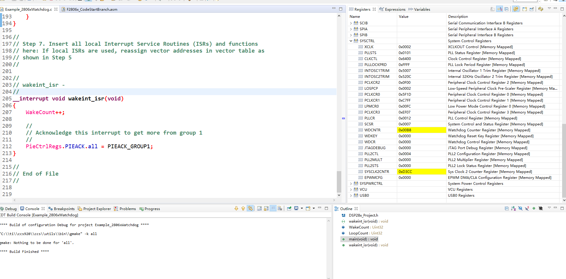
I see that the watchdog's counter keeps increasing and even has overflowed, but the system just doesn't reset.
I added the configuration in the watchdog routine in the official dual motor routine
//###########################################################################
//
// FILE: Example_2806xWatchdog.c
//
// TITLE: Watchdog interrupt Test Example
//
//! \addtogroup f2806x_example_list
//! <h1>Watchdog interrupt Test(watchdog)</h1>
//!
//! This program exercises the watchdog.
//!
//! First the watchdog is connected to the WAKEINT interrupt of the
//! PIE block. The code is then put into an infinite loop.
//!
//! The user can select to feed the watchdog key register or not
//! by commenting the following line of code in the infinite loop:
//! \b ServiceDog(); \n
//!
//! If the watchdog key register is fed by the ServiceDog function
//! then the WAKEINT interrupt is not taken. If the key register
//! is not fed by the ServiceDog function then WAKEINT will be taken.
//!
//! \b Watch \b Variables \n
//! - \b LoopCount , for the number of times through the infinite loop
//! - \b WakeCount , for the number of times through WAKEINT
//
//###########################################################################
// $TI Release: F2806x Support Library v2.04.00.00 $
// $Release Date: Fri May 24 03:37:28 CDT 2019 $
// $Copyright:
// Copyright (C) 2009-2019 Texas Instruments Incorporated - http://www.ti.com/
//
// Redistribution and use in source and binary forms, with or without
// modification, are permitted provided that the following conditions
// are met:
//
// Redistributions of source code must retain the above copyright
// notice, this list of conditions and the following disclaimer.
//
// Redistributions in binary form must reproduce the above copyright
// notice, this list of conditions and the following disclaimer in the
// documentation and/or other materials provided with the
// distribution.
//
// Neither the name of Texas Instruments Incorporated nor the names of
// its contributors may be used to endorse or promote products derived
// from this software without specific prior written permission.
//
// THIS SOFTWARE IS PROVIDED BY THE COPYRIGHT HOLDERS AND CONTRIBUTORS
// "AS IS" AND ANY EXPRESS OR IMPLIED WARRANTIES, INCLUDING, BUT NOT
// LIMITED TO, THE IMPLIED WARRANTIES OF MERCHANTABILITY AND FITNESS FOR
// A PARTICULAR PURPOSE ARE DISCLAIMED. IN NO EVENT SHALL THE COPYRIGHT
// OWNER OR CONTRIBUTORS BE LIABLE FOR ANY DIRECT, INDIRECT, INCIDENTAL,
// SPECIAL, EXEMPLARY, OR CONSEQUENTIAL DAMAGES (INCLUDING, BUT NOT
// LIMITED TO, PROCUREMENT OF SUBSTITUTE GOODS OR SERVICES; LOSS OF USE,
// DATA, OR PROFITS; OR BUSINESS INTERRUPTION) HOWEVER CAUSED AND ON ANY
// THEORY OF LIABILITY, WHETHER IN CONTRACT, STRICT LIABILITY, OR TORT
// (INCLUDING NEGLIGENCE OR OTHERWISE) ARISING IN ANY WAY OUT OF THE USE
// OF THIS SOFTWARE, EVEN IF ADVISED OF THE POSSIBILITY OF SUCH DAMAGE.
// $
//###########################################################################
//
// Included Files
//
#include "DSP28x_Project.h" // Device Headerfile and Examples Include File
//
// Function Prototypes
//
__interrupt void wakeint_isr(void);
//
// Globals
//
Uint32 WakeCount;
Uint32 LoopCount;
//
// Main
//
void main(void)
{
//
// Step 1. Initialize System Control:
// PLL, WatchDog, enable Peripheral Clocks
// This example function is found in the F2806x_SysCtrl.c file.
//
InitSysCtrl();
//
// Step 2. Initalize GPIO:
// This example function is found in the F2806x_Gpio.c file and
// illustrates how to set the GPIO to it's default state.
//
// InitGpio(); // Skipped for this example
//
// Step 3. Clear all interrupts and initialize PIE vector table:
// Disable CPU interrupts
//
DINT;
//
// Initialize PIE control registers to their default state.
// The default state is all PIE interrupts disabled and flags
// are cleared.
// This function is found in the F2806x_PieCtrl.c file.
//
InitPieCtrl();
//
// Disable CPU interrupts and clear all CPU interrupt flags
//
IER = 0x0000;
IFR = 0x0000;
//
// Initialize the PIE vector table with pointers to the shell Interrupt
// Service Routines (ISR).
// This will populate the entire table, even if the interrupt
// is not used in this example. This is useful for debug purposes.
// The shell ISR routines are found in F2806x_DefaultIsr.c.
// This function is found in F2806x_PieVect.c.
//
InitPieVectTable();
//
// Interrupts that are used in this example are re-mapped to
// ISR functions found within this file.
//
EALLOW; // This is needed to write to EALLOW protected registers
PieVectTable.WAKEINT = &wakeint_isr;
EDIS; // This is needed to disable write to EALLOW protected registers
//
// Step 4. Initialize all the Device Peripherals:
// This function is found in F2806x_InitPeripherals.c
//
//InitPeripherals(); // Not required for this example
//
// Step 5. User specific code, enable interrupts
//
//
// Clear the counters
//
WakeCount = 0; // Count interrupts
LoopCount = 0; // Count times through idle loop
//
// Connect the watchdog to the WAKEINT interrupt of the PIE
// Write to the whole SCSR register to avoid clearing WDOVERRIDE bit
//
EALLOW;
SysCtrlRegs.SCSR = BIT1;
EDIS;
//
// Enable WAKEINT in the PIE: Group 1 interrupt 8
// Enable INT1 which is connected to WAKEINT:
//
PieCtrlRegs.PIECTRL.bit.ENPIE = 1; // Enable the PIE block
PieCtrlRegs.PIEIER1.bit.INTx8 = 1; // Enable PIE Gropu 1 INT8
IER |= M_INT1; // Enable CPU INT1
EINT; // Enable Global Interrupts
//
// Reset the watchdog counter
//
ServiceDog();
//
// Enable the watchdog
//
EALLOW;
SysCtrlRegs.WDCR = 0x0028;
EDIS;
//
// Step 6. IDLE loop. Just sit and loop forever (optional)
//
for(;;)
{
LoopCount++;
//
// Uncomment ServiceDog to just loop here
// Comment ServiceDog to take the WAKEINT instead
//
// ServiceDog();
}
}
//
// Step 7. Insert all local Interrupt Service Routines (ISRs) and functions
// here: If local ISRs are used, reassign vector addresses in vector table as
// shown in Step 5
//
//
// wakeint_isr -
//
__interrupt void wakeint_isr(void)
{
WakeCount++;
//
// Acknowledge this interrupt to get more from group 1
//
PieCtrlRegs.PIEACK.all = PIEACK_GROUP1;
}
//
// End of File
//