A related question is a question created from another question. When the related question is created, it will be automatically linked to the original question.
If you have a related question, please click the "Ask a related question" button in the top right corner. The newly created question will be automatically linked to this question.
[FAQ] CCS/TDA4VM: Pinmux Guide for Jacinto Processors
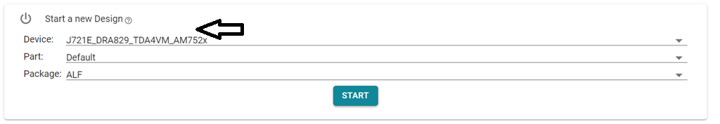
In the “Start a new Design” Pick an existing design that matches your part number . Ex: J721E_DRA829_TDA4VM_AM752x Keep the “Part” tab default & “Package” ALF. Click “Start” button. As shown in the screenshot below:
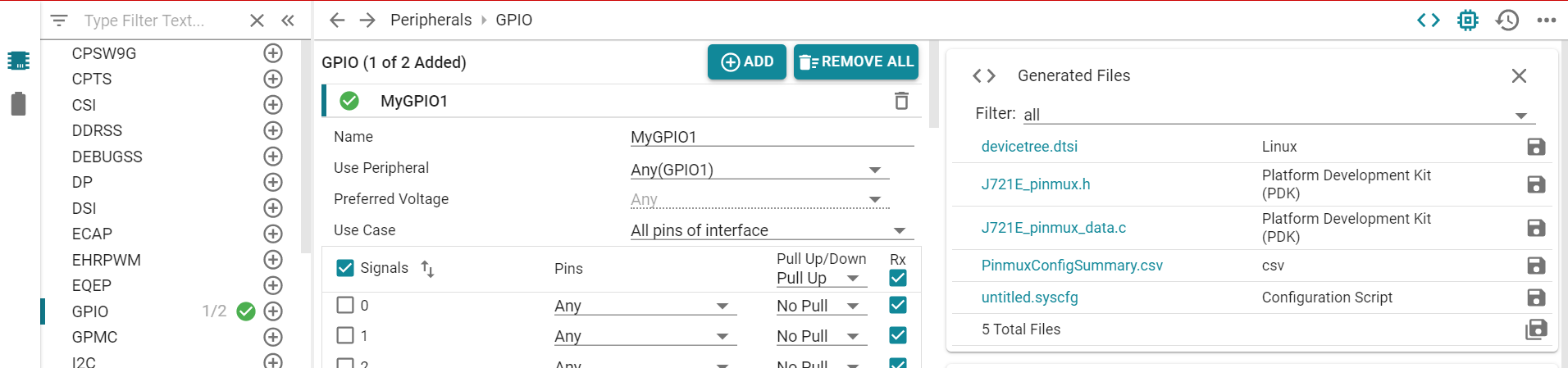
Choose the peripheral by entering the corresponding name in the “Type Filter Text” (Left top of the page). ex: GPIO & Click “+” sign. This will add a module on the center.
MyGPIO1 will have some defaults. Choose the exact module instance in the “Use peripheral” menu. By default it will be ANY. Select the appropriate instance using the drop down menu. Ex: In our case let’s say: GPIO0
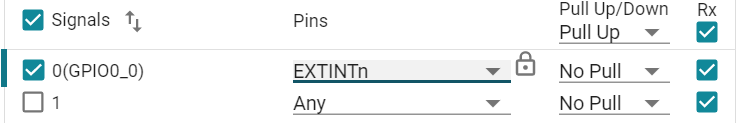
With this, we are done with module level selection. Now we just need to pick the ball name that maps to the one present in the board schematics. This can be accomplished by choosing the right ball name in the “Pins” drop down menu. Based on schematics pick appropriate “Pull Up/Down” from the drop down menu. Ex: Refer the Manual audit section below on how we pick the pin name EXTINTn
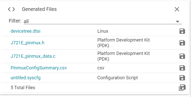
From the “Generated Files” section, based on the choice of OS, download one of these files: - Linux: devicetree.dtsi: Just need to copy paste the node as is under the right parent pinmux node (see below for details) - PDK(RTOS): J721E_pinmux.h/ J721E_pinmux.c
Ex: Linux: devicetree.dtsi. We have chosen main gpio0 hence the pinmux node for the example mygpio1_pins_default should come under main_pmx0 node in arch/arm64/boot/dts/ti/j721-common-proc-board.dts file.
/* This file was auto-generated by TI PinMux on 7/22/2020 at 9:21:31 AM. */
/* This file should only be used as a reference. Some pins/peripherals, */
/* depending on your use case, may need additional configuration. */

&main_pmx0 {
                            mygpio1_pins_default: mygpio1_pins_default {
                                           pinctrl-single,pins = <
                                                         J721E_IOPAD(0x0, PIN_INPUT, 7) /* (AC18) EXTINTn.GPIO0_0 */
                                           >;
                            };
};
The same can be followed with u-boot device tree. The very same example arch/arm/dts/j721-common-proc-board.dts file
The first instance of search lands in the table which gives the Ball number and name which is what we need to check in board schematics to see on which Ball the gpio0_0 is brought out on the board. Just for example: AC18 maps to for GPIO0_0. Page: 15: AC18
Search for AC18 which maps on to a padconfig register as below. In the PADCONFIG0 register in the Data Manual search for AC18 and that is the mode that needs to be programmed. ex: gpio0_0 is mode7 and hence the pinmux files should have mode7 to bring out gpio0_0 signal out of ball AC18. Page: 133
We can tally the devicetree.dtsi generated by the pinmux tool & manually audited register & the bit fields & cross verify. Ex: J721E_IOPAD(0x0, PIN_INPUT, 7) 0x0 corresponds to register offset 0x0 for PADCONFIG0 register & 7 corresponds to mux mode7