This thread has been locked.

If you have a related question, please click the "Ask a related question" button in the top right corner. The newly created question will be automatically linked to this question.

Source oscillator frequency multiplier by 12000

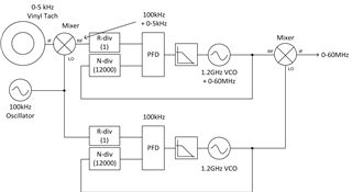
I have a free software and hardware project  (RAM platter hybrid) which requires a low frequency source oscillator to have its frequency multiplied up 12000  times. It is possible that this is a good application for DDS or a VCO+PLL.

The source oscillator ranges between 0 Hz and 5 kHz. The most common rate of the source oscillator (f0) is 1 kHz.

The implication of the 12000 frequency multiplier is that the target output signal frequency is from 0 Hz to 60 MHz. Exact 0 Hz output is not necessary but desireable. Close to 0 Hz is very desirable, but 1 Hz or 10 Hz is ok.

As the platter is interfaced by a human, the source tone is extremely band limited in its ability to change. For that reason the rate of change of the source oscillator is slow. For example, a normal rate of change is limited by the speed of a persons hand moving - that may be at a rate of 1 or 2 kHz per second.

Extreme jitter control when the source oscillator is idling is not necessary as the platter is a heavy flywheel (a turntable's platter) and this should mitigate a certain amount of jitter in the source oscillator's signal. It would be an advantage however if jitter reduction was possible. 

  • Hi flatmax,

    PLLs only work when you provide them with enough reference cycles for a decent comparison. While there's some work being done with digital PLLs to minimize the time to lock to low-frequency signals, none of the DPLLs we could give you would be good choices for this kind of wide-reference application. You could build your own in an FPGA, but something tells me this is beyond the scope of what you want to do.

    From a PLL standpoint, you'd be much better off if you could establish a much-higher fixed-frequency and mix up the 0-5kHz signal so that the loop bandwidth of the PLL could support the desired rate of change. For example: if you can mix the 0-5kHz signal onto a fixed 100kHz oscillator, then multiply this signal up by a factor of 12k, your output would be a 1.2GHz signal with up to 60MHz of error. You could run a parallel PLL with a 12k multiplication factor off the same 100kHz oscillator but without the mixed-up 0-5kHz signal, and the result would be a fixed 1.2GHz signal with no error. Then you could mix the 1.2GHz + error with the 1.2GHz fixed and extract a 0-60MHz clock, which would continuously shift in frequency directly proportional to the 0-5kHz reference.

    You could also break this up into a few stages, so that you're not multiplying up by a factor of 12k in a single PLL (this would cause lots of issues with cycle slip at the phase detector). Conceptually you can use the same scheme cascaded so you're only multiplying up by a factor of 100 and 120 in two stages - this requires more components and more PLLs, but there's virtually no concerns with cycle slip and the reference oscillators can be more realistic e.g. 10MHz. This also minimizes the tuning range required at each VCO.

    All that said: given that the frequency range is 0-5kHz, there isn't too much that can be done about jitter cleaning with this approach since by definition we have to be tracking the 1-2kHz/s change in reference frequency (corresponding to at least 5kHz loop bandwidth, ideally more like 10kHz) - we can't adequately filter the sideband without tracking it, and we can't track it without keeping the loop bandwidth too high to filter it. Multiplying up by a factor of 12k also means multiplying up the jitter by a factor of 12k, so your clock signal will be pretty terrible quality even if you can get this approach working (at least as far as an audio ADC/DAC is concerned). Am I correct in inferring that your reference oscillator is basically a tachometer from the reference platter? I strongly doubt you could generate a clean enough clock from a motor signal, regardless of the flywheel effects that should theoretically be filtering transient noise, because the 1/f inherent in the motor drive for thermal reasons is going to be too high in-band (especially once multiplied up by 12k). Do not underestimate the effect of this 12k factor on the jitter: the whole signal's phase noise will increase by 20 * log(12k) = more than 80dB in-band, and it's not great to begin with. The induced phase error will be audible at steady state if the audio clock is coming from a motor drive. On the other hand, if your reference signal is synthesized from some high-quality source and is a software-generated proxy for the motor speed, this could work well - but at that point there's a more direct approach.

    I think what you really want is the ability to rapidly and accurately predict the platter frequency from a limited number of samples. I don't think you need to directly couple the platter to the clock, and for the reasons stated above it tends to be a tough sell anyway. On the other hand, you can dictate the flywheel dynamics and you can probably sense the force being applied to it with some kind of magnetic field monitoring or back EMF sensing. If you can sample these signals really fast, you could come up with a model of the predicted angular velocity of the platter, and use it to dynamically adjust the frequency output of a DDS. This approach has some error, but if you can update the DDS faster than audio frequency you should be able to push the quantization error above the audio cutoff, leaving only the model error in-band. And since you're sampling really fast, you can continuously update the model and generate better coefficients at all times. The control loop here is more complex, but the benefit is you can use a fixed-frequency and low-jitter reference source for your DDS, so your frequency-sensing scheme no longer adds to the clock noise on the Audio ADC/DAC. And if your processor doing the modeling is fast enough, this is still a real-time control loop rather than high-latency post-processing in a DSP. Unfortunately, this would burden the CPU unless offloaded to a dedicated controller; and high-performance DDS is not exactly low-power or low-cost.

    Maybe there's a hybrid approach where you switch signals between a very clean 1kHz while the platter is at nominal frequency, and something like the synthesizer/mixer approach described above while the platter is being manipulated. You still have a low-quality clock driving the audio source during frequency shifting, but unless you apply a near-constant force to the platter to induce a specific pitch shift, perhaps the act of variably shifting pitch itself may end up making the clock quality issues less audible. Personally I doubt that it would work like this, but that's just a gut feeling - it is otherwise something to consider.

    Very neat idea, with a lot of interesting challenges to solve.

    Regards,

    Derek Payne

  • Hi Derek,

    Thank you very much for the detailed answer. It is clear to me now that the range of input frequencies is too large for a PLL to manage and a complete rethink/redesign is necessary.

    The actual source for the frequencies is a vinyl on the platter. The vinyl has quadrature offset tones at 1 kHz. The person can use their hand to speed up and slow down the vinyl in effect speeding up and slowing down the waveform. The desired master clock frequency for the audio codec is 12 MHz when the vinyl frequency is at 1 kHz.

    I guess it is possible to limit the input frequency range somewhat, for example 10 Hz to 3 kHZ, but I doubt that will bring the requirements into a suitable PLL+VCO range.

    I didn't quite understand the mix up discussion below. I'm not from an RF background, although I find this area fascinating. Could you please restate the idea below again ?

  • flatmax,

    In case you are unfamiliar, a mixer is a device which combines two frequencies to produce a third frequency, based on the results of some trigonometric identities. In this case (the most common), the mixer implements addition and subtraction. Typically we refer to a mixer by the RF port (high frequency), the IF port (intermediate frequency) and the LO port (local oscillator frequency). The operational direction of the mixer can vary, such that either RF or IF ports can be the input or output.

    I've drawn a diagram representing my first mixer suggestion. To keep matters simple, there are two identical PLL circuits. One generates 1.2GHz from 100kHz; the other generates 1.2GHz + up to 60MHz from 100kHz + up to 5kHz. A mixer would be used to combine the 100kHz reference and the 0-5kHz signal from the tachometer, such that the signal seen at the phase detector is now 100kHz to 105kHz (much smaller variation relative to nominal frequency). Furthermore, now there is only 5kHz * 12000 = 60MHz of variation at the VCO, which can definitely be within the tuning range of the VCO. The first PLL locks to the 100kHz to 105kHz signal and produces 1.2GHz to 1.26GHz at the VCO output. The loop bandwidth of this PLL can be made greater than 5kHz which should be acceptable for tracking the 1-2kHz/s change at the tachometer. Meanwhile, the second PLL is identical to the first, but has a fixed frequency input and output. The resulting VCO outputs are combined at a subsequent mixer operating as a subtractor, so that 1.2GHz is subtracted from the RF port and the 0-60MHz multiplied-up component is all that remains. In practice you would also want antialiasing filters on both the input and output to prevent locking to 100kHz - 0-5kHz, and to eliminate the sum of the two VCOs. Eliminating the VCO sums is easy; eliminating the difference at the mixer can be more tricky, but some mixer designs can more favorably produce a sum or a difference specifically and suppress the other unwanted function.

    The drawback of this scheme is that the VCO is operating at very high frequency relative to the PFD frequency, so changes at the VCO take a long time to propagate through the N-divider. If it takes long enough, the PFD may "cycle slip" when the N-divider reverts its phase relative to the R-divider before the VCO can bring the feedback path into alignment again. Cycle slipping slows down the loop considerably, and although a stable loop can recover, it can be difficult to keep up with rapid changes at the reference (even when the loop bandwidth is theoretically high enough). This means you may not track the full 1-2kHz/s rate of change as desired.

    As I mentioned, if you break this scheme up into two segments with lower multiplication ratios (e.g. 100 and 120), cycle-slipping is much less of an issue since the PFD can operate at a much higher rate without requiring terrifically high VCO frequency, and the LO can now be at a more ubiquitous frequency than 100kHz (e.g. 10MHz). Another image detailing the cascaded scheme is shown below.

    Regards,

    Derek Payne

  • This looks like a great concept. I am willing to try it.
    Can you advise on any chips which can implement each of the sections ? 

  • flatmax,

    TI doesn't sell any discrete mixers, but these devices can be commonly found from multiple distributors and manufacturers. I'd start with MiniCircuits, as their selection tends to be wide. You may be able to use the same mixer part number for every element. You're looking for a mixer which can upconvert up to >10MHz, and downconvert >1.2GHz.

    10MHz reference oscillators are fairly ubiquitous on distributors, so I guess pick the best tradeoff between jitter and performance. Remember the jitter will be multiplied up considerably, so a higher quality 10MHz XO would be my typical recommendation... in practice, as I mentioned before, I think the dominant noise source is going to be the 0-5kHz signal so in the end it may not matter that much.

    For the PLLs, you can likely find a device with an integrated VCO. Something like LMX2572LP looks ideal. The integrated VCO range is a little high (3.2-6.4GHz) but it includes a channel divider so that 1GHz or 1.2GHz could be synthesized from 4GHz or 4.8GHz respectively. We also have two tools: TICS Pro, to help prototype the register settings for the device (and forewarn of potential issues); and PLLatinum Sim, which can be used to help design a stable loop filter at the appropriate bandwidth.

    Regards,

    Derek Payne

  • Thanks again Derek, I'll start designing and hit up the forum when I need help.

    I would like to use the TICS Pro software, however I can't because I use Linux.

  • flatmax,

    TICS Pro has some windows USB stack dependencies that make it sort of hard to get working on Linux. I don't have a great suggestion for how to work around this today, but it's something we're working on (might take a few years before we have a good answer though). Since it seems very challenging to do all the programming, I drafted a couple of hex register configurations for the 1GHz and 1.2GHz cases in the cascade configurations (the "all in one" configuration is a bit too far beyond the usable input frequency range).

    HexRegisterValues-1.2GHz.txt
    R125	0x7D0820
    R124	0x7C0000
    R123	0x7B0000
    R122	0x7A0000
    R121	0x790000
    R120	0x780000
    R119	0x770000
    R118	0x760000
    R117	0x750000
    R116	0x740000
    R115	0x730000
    R114	0x727802
    R113	0x710000
    R112	0x700000
    R111	0x6F0000
    R110	0x6E0000
    R109	0x6D0000
    R108	0x6C0000
    R107	0x6B0000
    R106	0x6A0007
    R105	0x694440
    R104	0x680000
    R103	0x670000
    R102	0x660000
    R101	0x650000
    R100	0x640000
    R99	0x630000
    R98	0x620000
    R97	0x610000
    R96	0x600000
    R95	0x5F0000
    R94	0x5E0000
    R93	0x5D0000
    R92	0x5C0000
    R91	0x5B0000
    R90	0x5A0000
    R89	0x590000
    R88	0x580000
    R87	0x570000
    R86	0x560000
    R85	0x550000
    R84	0x540000
    R83	0x530000
    R82	0x520000
    R81	0x510000
    R80	0x500000
    R79	0x4F0000
    R78	0x4E0001
    R77	0x4D0000
    R76	0x4C000C
    R75	0x4B0840
    R74	0x4A0000
    R73	0x49003F
    R72	0x480001
    R71	0x470081
    R70	0x46C350
    R69	0x450000
    R68	0x4403E8
    R67	0x430000
    R66	0x4201F4
    R65	0x410000
    R64	0x401388
    R63	0x3F0000
    R62	0x3E00AF
    R61	0x3D00A8
    R60	0x3C03E8
    R59	0x3B0001
    R58	0x3A9001
    R57	0x390020
    R56	0x380000
    R55	0x370000
    R54	0x360000
    R53	0x350000
    R52	0x340421
    R51	0x330080
    R50	0x320080
    R49	0x314180
    R48	0x3003E0
    R47	0x2F0300
    R46	0x2E07F0
    R45	0x2DC608
    R44	0x2C08A0
    R43	0x2B0000
    R42	0x2A0000
    R41	0x290000
    R40	0x280000
    R39	0x2703E8
    R38	0x260000
    R37	0x250105
    R36	0x2401E0
    R35	0x230004
    R34	0x220010
    R33	0x211E01
    R32	0x2005BF
    R31	0x1FC3E6
    R30	0x1E0CA6
    R29	0x1D0000
    R28	0x1C0488
    R27	0x1B0002
    R26	0x1A0808
    R25	0x190624
    R24	0x18071A
    R23	0x17007C
    R22	0x160001
    R21	0x150409
    R20	0x144848
    R19	0x1327B7
    R18	0x120064
    R17	0x110096
    R16	0x100080
    R15	0x0F060E
    R14	0x0E1820
    R13	0x0D4000
    R12	0x0C5001
    R11	0x0BB018
    R10	0x0A10F8
    R9	0x090004
    R8	0x082000
    R7	0x0700B2
    R6	0x06C802
    R5	0x0530C8
    R4	0x040A43
    R3	0x030782
    R2	0x020500
    R1	0x010808
    R0	0x00201C
    

    HexRegisterValues-1GHz.txt
    R125	0x7D0820
    R124	0x7C0000
    R123	0x7B0000
    R122	0x7A0000
    R121	0x790000
    R120	0x780000
    R119	0x770000
    R118	0x760000
    R117	0x750000
    R116	0x740000
    R115	0x730000
    R114	0x727802
    R113	0x710000
    R112	0x700000
    R111	0x6F0000
    R110	0x6E0000
    R109	0x6D0000
    R108	0x6C0000
    R107	0x6B0000
    R106	0x6A0007
    R105	0x694440
    R104	0x680000
    R103	0x670000
    R102	0x660000
    R101	0x650000
    R100	0x640000
    R99	0x630000
    R98	0x620000
    R97	0x610000
    R96	0x600000
    R95	0x5F0000
    R94	0x5E0000
    R93	0x5D0000
    R92	0x5C0000
    R91	0x5B0000
    R90	0x5A0000
    R89	0x590000
    R88	0x580000
    R87	0x570000
    R86	0x560000
    R85	0x550000
    R84	0x540000
    R83	0x530000
    R82	0x520000
    R81	0x510000
    R80	0x500000
    R79	0x4F0000
    R78	0x4E0001
    R77	0x4D0000
    R76	0x4C000C
    R75	0x4B0840
    R74	0x4A0000
    R73	0x49003F
    R72	0x480001
    R71	0x470081
    R70	0x46C350
    R69	0x450000
    R68	0x4403E8
    R67	0x430000
    R66	0x4201F4
    R65	0x410000
    R64	0x401388
    R63	0x3F0000
    R62	0x3E00AF
    R61	0x3D00A8
    R60	0x3C03E8
    R59	0x3B0001
    R58	0x3A9001
    R57	0x390020
    R56	0x380000
    R55	0x370000
    R54	0x360000
    R53	0x350000
    R52	0x340421
    R51	0x330080
    R50	0x320080
    R49	0x314180
    R48	0x3003E0
    R47	0x2F0300
    R46	0x2E07F0
    R45	0x2DC608
    R44	0x2C08A0
    R43	0x2B0000
    R42	0x2A0000
    R41	0x290000
    R40	0x280000
    R39	0x2703E8
    R38	0x260000
    R37	0x250105
    R36	0x240190
    R35	0x230004
    R34	0x220010
    R33	0x211E01
    R32	0x2005BF
    R31	0x1FC3E6
    R30	0x1E0CA6
    R29	0x1D0000
    R28	0x1C0488
    R27	0x1B0002
    R26	0x1A0808
    R25	0x190624
    R24	0x18071A
    R23	0x17007C
    R22	0x160001
    R21	0x150409
    R20	0x144848
    R19	0x1327B7
    R18	0x120064
    R17	0x110096
    R16	0x100080
    R15	0x0F060E
    R14	0x0E1820
    R13	0x0D4000
    R12	0x0C5001
    R11	0x0BB018
    R10	0x0A10F8
    R9	0x090004
    R8	0x082000
    R7	0x0700B2
    R6	0x06C802
    R5	0x0530C8
    R4	0x040A43
    R3	0x030782
    R2	0x020500
    R1	0x010808
    R0	0x00201C
    

    PLLatinum Sim doesn't have any deeply-embedded Windows dependencies, so it may run in an emulator, a windows->linux syscall translation layer, or on a virtual machine without complaints. Again, this is something we're working on (again, timescale is likely years out).

    Regards,

    Derek Payne