Part Number: AFE7422EVM
Hello,
I have a next issue with AFE7422 EVM.
I'm trying to bring up AFE7422 together with TSW14J57EVM. I have successfully passed through video#3: How to configure the AFE74xx DAC in Mode 4 using the internal PLL and now I'm able to see a tones at the DAC output on my spectrum analyzer.
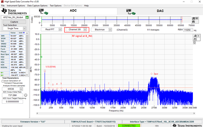
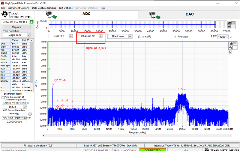
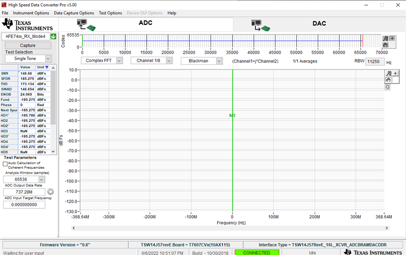
But when I moving forward trying to replicate the actions from video #4 (How to configure the AFE74xx ADC in Mode 4 using the internal PLL) I cannot see anything captured from the ADC. This is what I see after pressing "Capture" button:
As it is mentioned in the bringup video I have tried to press this button:
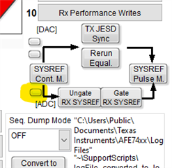
and pressed "Capture" again, but it doesn't help.
Additional question:
In the bringup videos I see that the spectrum analyzer is connected to J23 IOUTB:
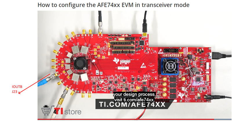
But I see the output tones at the J22 IOUTA - is that normal?
In a connection to this, I have tried to connect an input signal (from my RF signal source) to both A_IN1 and A_IN2 but no any capture received.
Please help to understand what we doing wrong.
Regards,
Eugene
Please help to understand what I doing