This thread has been locked.

If you have a related question, please click the "Ask a related question" button in the top right corner. The newly created question will be automatically linked to this question.

AFE7422EVM: What is the proper way to configure AFE7422 to the RX Mode 1?

Part Number: AFE7422EVM

Hi,

I have a problem when trying to configure AFE7422EVM to the RX Mode 1.

What I'm going after powering on:

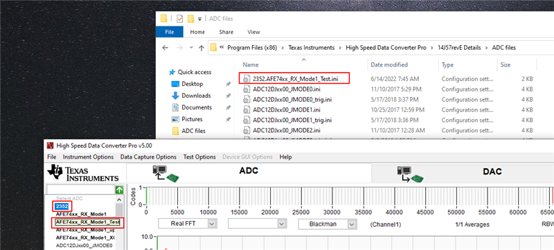
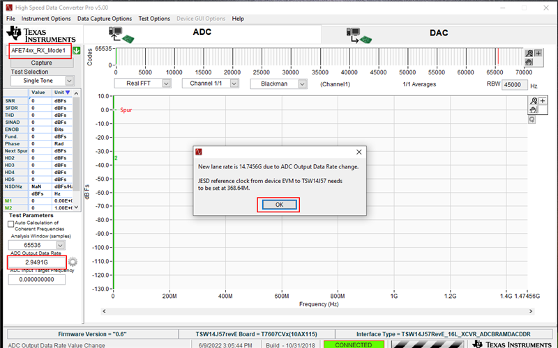
1) in HSDC Pro selecting RX Mode 1 and setting ADC output data rate to 2949.12M:

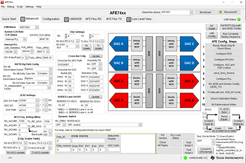
2) In AFE GUI pressing Set Mode and Run Complete... buttons:
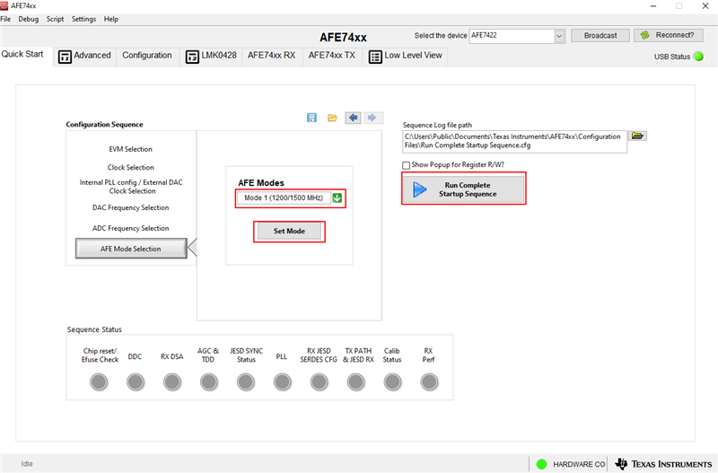
 afe74

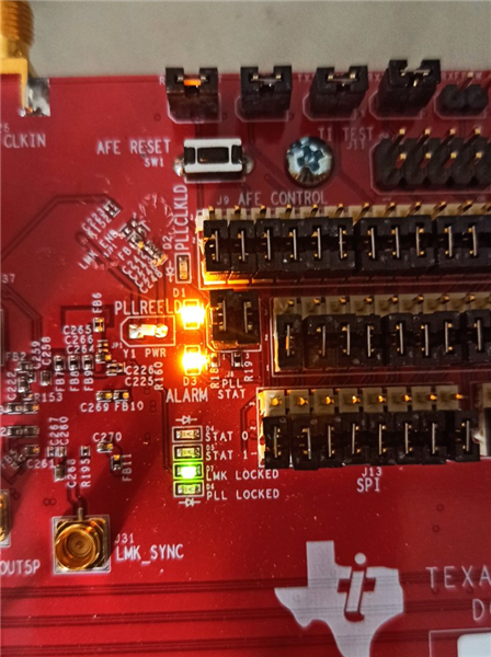
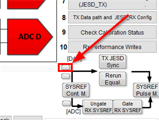
After these actions I see LED D4 is blinking on TSW board, but on AFE board - all 3x LEDs going ON: D1, D2 and D3 (ALARM).

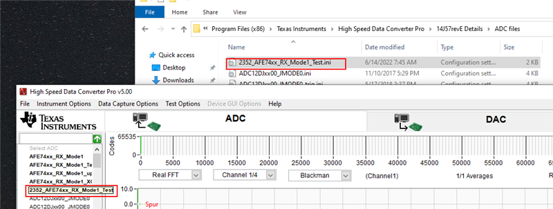
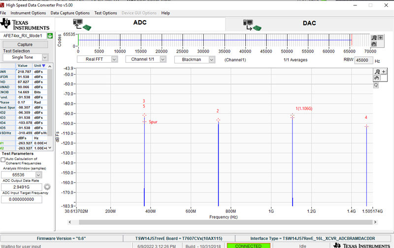
This is the capture I see in HSDC Pro:

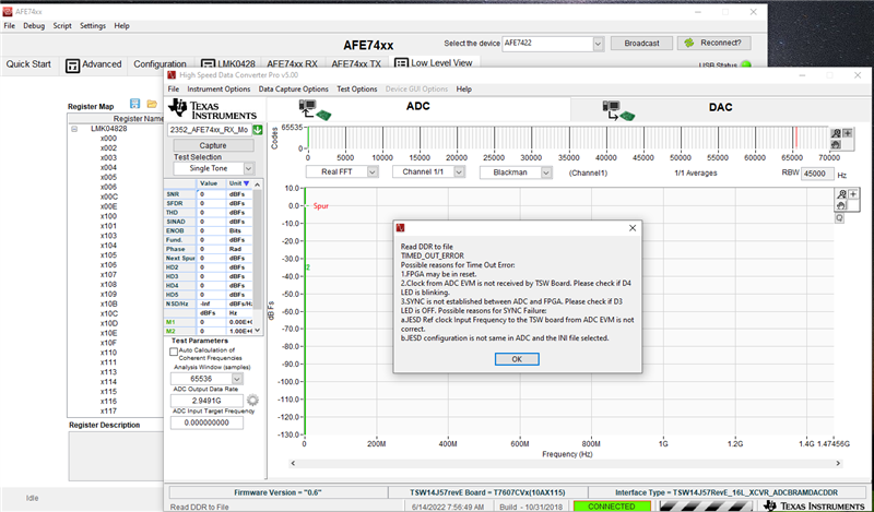
I have checked this thread (with similar issue as I believe), and after loading AFE7422_InternalCLK_Mode 1_BW_Bypass_SingBand_Fdac_9G_Fadc_3G_RX_82240_TX84111.cfg 

to the AFE ALARM LED going to be OFF, but I'm getting the following error message after pressing Capture:

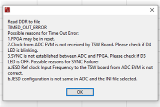
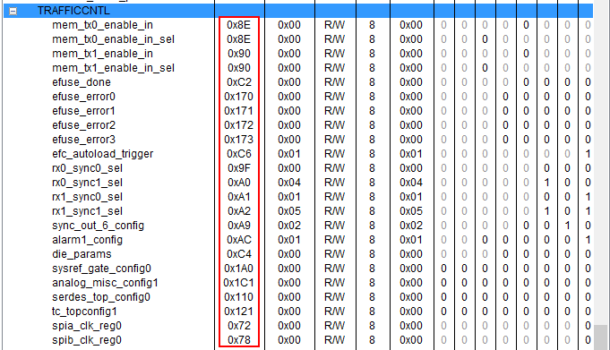
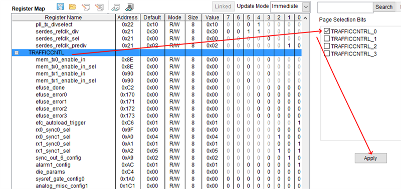
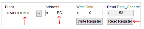
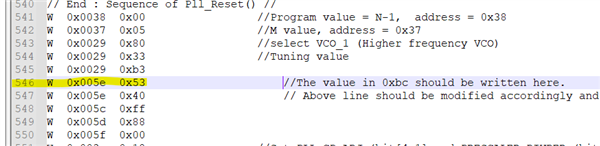
This is what Advanced tab shows:

Best Regards,

Eugene

  • Hi Eugene,

    We are looking into this for you. I will loop the right apps engineer in to help you on this.

    Regards,

    Rob

  • Hi Eugene,

    Please use the following configuration file to program the AFE7422 in Mode 1. To load this config file you have to go to the Low Level View tab and select Open Configuration button.

    2543.AFE7422_InternalCLK_Mode 1_BW_Bypass_SingBand_Fdac_9G_Fadc_3G_RX_82240_TX84111.cfg

    Please use the following ini file to capture the ADC data. To use this file please close HSDC pro and copy the ini file to this location: C:\Program Files (x86)\Texas Instruments\High Speed Data Converter Pro\14J57revE Details\ADC files 

    2352.AFE74xx_RX_Mode1_Test.ini

    Regards,

    David Chaparro 

  • Hi David,

    Thanks for the config files. I have tested it but it doesn't help.

    First of all I cannot directly use 2352.AFE74xx_RX_Mode1_Test.ini filename because of the dot after "2543" - HSDC GUI produces two config entries: 

    - 2543

    and

    - AFE74xx_RX_Mode1_Test

    and as I already have another AFE74xx_RX_Mode1_Test.ini in the folder this leads to the confusion:

    So I have renamed 2352.AFE74xx_RX_Mode1_Test.ini to 2352_AFE74xx_RX_Mode1_Test.ini to get only one string in the list of the configs:

    The test. 

    After choosing 2352_AFE74xx_RX_Mode1_Test I'm:

    - setting ADC output data rate to 2949.12M

    - in AFE GUI in low level loading 2543.AFE7422_InternalCLK_Mode 1_BW_Bypass_SingBand_Fdac_9G_Fadc_3G_RX_82240_TX84111.cfg

    Results:

    - ALARM LED is still ON. Other LED states:


    RX LED on TSW board doesn't blink and error message appears after pressing "Capture" button:

    Maybe I doing some wrong action? Can you please check?

    Also I have some additional questions:

    1) As I can see loading the registers through the low level tab doesn't affecting to the state of the controls in the "Advanced" tab. Is this correct? If yes - how can I tune up the AFE after loading the registers from cfg file? Can I change the controls in the "Advanced" tab after loading cfg? What configuration routine should I follow in this case?

    2) Actually our goal is to use the AFE+TSW as a Transceiver in Mode1 - we need to send our own test files through the DAC and receive it with ADC. Can we do this using the files you send? Which file should I use to setup the DAC to TX Mode1 together with 2352_AFE74xx_RX_Mode1_Test?


    Best Regards,

    Eugene Kim

  • Hi Eugene,

    I would suggest removing the '2352 and 2342' from the file names. The files names were somehow modified after I posted the files in my reply.

    In order for the PLL to lock there is one additional step that must be followed. After running the config file you have to read back register 0xbc in the TRAFFICCNTRL page. This is a trim value for the VCO that is being used.

    The value that is read back must then be entered into register 0x5e of the TXPLLDIG page. The easiest solution is to update this register in the config file, Line 546, then load the config file again. 

    When loading a configuration file the advanced tab will not be updated to match the settings loaded. To modify the configuration would consist of updating the registers directly or modifying the configuration file.

    Using the files that I sent, you will be able to test the AFE7422 in the Mode1 configuration. The DAC ini file that you can use is the AFE74xx_TX_Mode1 that you already have installed. 

    Regards,

    David Chaparro

  • Hi David,

    There's a confusion with the following: i can't see the register with address 0xbc in this list:

    so please confirm if the following procedure of the reading of this register is correct:

    1) Click on TRAFFICCNTL and check TRAFFICCNTL_0 box, than press Apply:


    2) Select TRAFFICCNTL in this listbox and enter xBC into the address box, than press "Read":

    Following this procedure I've read 0x53 from this register.

    After that I have opened cfg and put 0x53 to the line 546:

    and loaded cfg once again.

    The result is the same - ALARM LED is on, PLL LED is off. Capture doesn't work.

    Can you please check what I'm doing wrong?

    Regards,

    Eugene

  • Eugene,

    The register is not shown in the low level tab.  The steps you show to select the TRAFFICCNTL block and enter the address are correct.

    Please delete line 547 as it is overwriting the value in register 0x5e. This will fix the error that you are seeing.

    Regards,

    David Chaparro 

  • Hi David,

    Yes, after removing the line 547 the capture starts working. But I have a couple of questions:

    1) As I can see in this configuration all frequency shifting is disabled - is this correct? So when I put 1GHz RF signal at the ADC input I will see it on capture at 1GHz.

    2) Still I cannot get anything from the DAC TX in this mode. My actions:

    - set ADC RX mode using 2352_AFE74xx_RX_Mode1_Test 

    - set ADC TX mode to AFE_74xx_TX_Mode1 (built in config file)

    - in DAC tab set Data Rate = 1.47456G

    - create a tone at center = 100MHz, press Create tone, press Send

    - load 2543.AFE7422_InternalCLK_Mode 1_BW_Bypass_SingBand_Fdac_9G_Fadc_3G_RX_82240_TX84111.cfg in AFE GUI

    - press Send again.

    is this correct procedure? 

    3) This is really not convenient to use low level files to configure the AFE/LMK. Yes, this makes the EVMs to be working with the particular settings, but this is completely disconnected from the interactive sections of the AFE GUI. So as a result we cannot evaluate the system interactively, and the GUI becomes to just a tool to load registers values from the text file to the AFE/LMK ICs. Is there any plans to make the GUI to be interactively operable for the XVR Mode1? If yes - when this can be expected?

    Thanks for your help,

    Eugene

  • Hi Eugene,

    You are correct that the frequency shifting is disabled with this configuration file. 

    The procedure that you are following should work. One thing to try is to re-sync the DAC JESD Link. This can be accomplished by pressing the following button in the GUI. Please note that the frequency shifting is disabled so the DAC output tone would appear near 100MHz, the tone center set in HSDC Pro.

    In regards to the GUI, we are working on debugging why the GUI does not program the AFE correctly into XVR Mode1. Once we have found the issue we will begin working on fixing the issue. We do not have a time frame at the moment as we will have to work with the 3rd party company who made the GUI.

    Regards,

    David Chaparro

  • Hi David,

    Thanks for your reply.

    I have made a little shorter test to check the TX in Mode1 after power On:

    - in HSDC Pro: select built-in AFE74xx_TX_Mode1

    - set Data Rate = 1.47456G SPS

    - create 2 tones around 100MHz

    - press Create Tones, Press Send

    - in AFE GUI: load 2543.AFE7422_InternalCLK_Mode 1_BW_Bypass_SingBand_Fdac_9G_Fadc_3G_RX_82240_TX84111.cfg

    - press Send again

    - re-sync the DAC JESD Link by pressing noname button in AFE GUI.

    So this procedure doesn't work. No signal observed at TX RF outputs and TX LED doesn't blink on TSW board.

    Can you please check?

    Best Regards,

    Eugene Kim

  • David,

    UPDATE:

    This procedure is working for TX Mode 1:

    - in HSDC Pro: select built-in AFE74xx_TX_Mode1

    - set Data Rate = 1.47456G SPS

    - create 2 tones around 100MHz

    - press Create Tones, Press Send

    - in AFE GUI: load 2543.AFE7422_InternalCLK_Mode 1_BW_Bypass_SingBand_Fdac_9G_Fadc_3G_RX_82240_TX84111.cfg

    - in AFE GUI select Mode 1 from Quick Start Tab

    - press Run Complete Sequence 

    - press Send again

    - re-sync the DAC JESD Link by pressing noname button in AFE GUI.

    After that TX LED starts blinking and I see tones at DAC output.

    Regards,

    Eugene

  • Hi Eugene,

    I will work on testing both of your procedures to see if there are any differences in the Tx output.

    Regards,

    David Chaparro

  • Ho David,

    Do you have any updates on this case? We need to use the kits in Mode1 with frequency shift enabled. Can you provide a way how to configure it in this mode and how to interactively change the RF frequency for TX and RX paths?

    Best Regards,

    Eugene