This thread has been locked.
If you have a related question, please click the "Ask a related question" button in the top right corner. The newly created question will be automatically linked to this question.
Hi Team,
I use these two boards for testing:AFE7950EVM + ZCU102 ,and using this resource: ZCU102-AFE79xx_8b10b10Gbps. I followed the instructions “TI204c-Setup.docx” in the document.
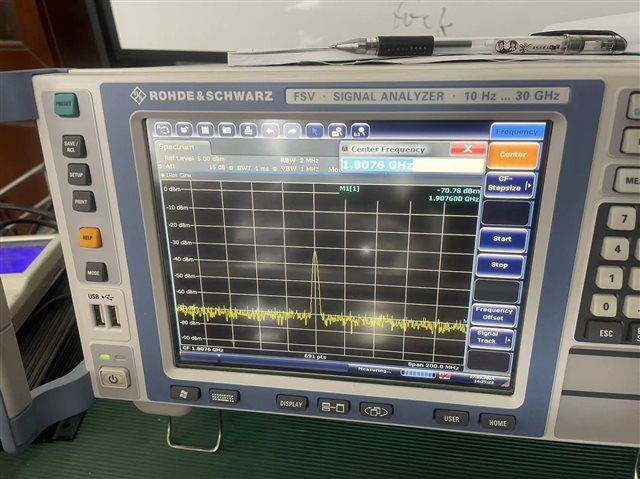
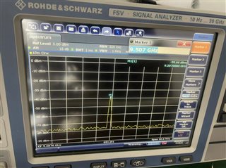
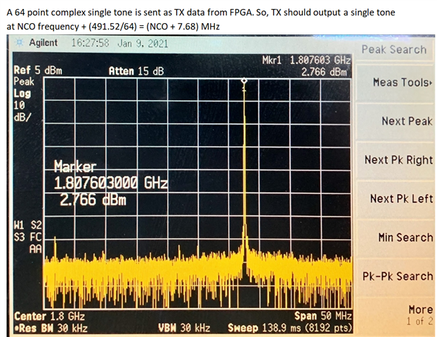
There is a question about the test results: When testing tx data from FPGA, the frequency measured by the spectrograph is the same as in the manual (1.8076GHz), but the signal amplitude is different. The signal amplitude in the manual is 2.7dbm, while my test result is around -32dbm.
My test result spectrum:
Hi Yake,
There are two factors that are causing the differences that you are seeing. The first being that the capture that is provided is from a AFE7900EVM, which has a balun and matching circuit for lower frequencies. The baluns on the AFE7950 have a frequency range of 4.7G to 12G and the matching circuits are matched for 9.5GHz.
The second factor is that the tone that is being sent to TxD, which is the channel I assume you are looking at, is not a full scale tone. The four DACs are receiving the same tone, but at different amplitudes. The picture that was provided was using a build where a full scale tone was being sent to TxD. To change this in your project you can update the following lines in the refdesign_tx.sv file:
assign tx_lane_data[0][63 -: 16] = sine_i[0][63 - sine_count*4]; assign tx_lane_data[0][47 -: 16] = sine_i[0][62 - sine_count*4]; assign tx_lane_data[0][31 -: 16] = sine_i[0][61 - sine_count*4]; assign tx_lane_data[0][15 -: 16] = sine_i[0][60 - sine_count*4]; assign tx_lane_data[1][63 -: 16] = sine_q[0][63 - sine_count*4]; assign tx_lane_data[1][47 -: 16] = sine_q[0][62 - sine_count*4]; assign tx_lane_data[1][31 -: 16] = sine_q[0][61 - sine_count*4]; assign tx_lane_data[1][15 -: 16] = sine_q[0][60 - sine_count*4]; assign tx_lane_data[2][63 -: 16] = sine_i[0][63 - sine_count*4]; assign tx_lane_data[2][47 -: 16] = sine_i[0][62 - sine_count*4]; assign tx_lane_data[2][31 -: 16] = sine_i[0][61 - sine_count*4]; assign tx_lane_data[2][15 -: 16] = sine_i[0][60 - sine_count*4]; assign tx_lane_data[3][63 -: 16] = sine_q[0][63 - sine_count*4]; assign tx_lane_data[3][47 -: 16] = sine_q[0][62 - sine_count*4]; assign tx_lane_data[3][31 -: 16] = sine_q[0][61 - sine_count*4]; assign tx_lane_data[3][15 -: 16] = sine_q[0][60 - sine_count*4]; assign tx_lane_data[4][63 -: 16] = sine_i[0][63 - sine_count*4]; assign tx_lane_data[4][47 -: 16] = sine_i[0][62 - sine_count*4]; assign tx_lane_data[4][31 -: 16] = sine_i[0][61 - sine_count*4]; assign tx_lane_data[4][15 -: 16] = sine_i[0][60 - sine_count*4]; assign tx_lane_data[5][63 -: 16] = sine_q[0][63 - sine_count*4]; assign tx_lane_data[5][47 -: 16] = sine_q[0][62 - sine_count*4]; assign tx_lane_data[5][31 -: 16] = sine_q[0][61 - sine_count*4]; assign tx_lane_data[5][15 -: 16] = sine_q[0][60 - sine_count*4]; assign tx_lane_data[6][63 -: 16] = sine_i[0][63 - sine_count*4]; assign tx_lane_data[6][47 -: 16] = sine_i[0][62 - sine_count*4]; assign tx_lane_data[6][31 -: 16] = sine_i[0][61 - sine_count*4]; assign tx_lane_data[6][15 -: 16] = sine_i[0][60 - sine_count*4]; assign tx_lane_data[7][63 -: 16] = sine_q[0][63 - sine_count*4]; assign tx_lane_data[7][47 -: 16] = sine_q[0][62 - sine_count*4]; assign tx_lane_data[7][31 -: 16] = sine_q[0][61 - sine_count*4]; assign tx_lane_data[7][15 -: 16] = sine_q[0][60 - sine_count*4];
When using the provided bit files and AFE7950EVM, we similar results of -32dBm from TxD. If you would like to see a higher amplitude then the first change should be to make the changes mentioned above then regenerate the bitfile.
Regards,
David Chaparro
Hi David,
Thank you for your detailed answer.
Our question is: if we change the balun and matching network for lower frequencies, say 1.8GHz, and send full scale tone to the Tx of AEF7950, could we see the same amplitude as shown on the AFE7900EVM? Essentially, we want to know at lower frequency, say 1.8GHz, does the AFE7950 chip itself output the same power as AFE7900?
Regards
Hi David,
I changed the NCO frequency of TxD channel to 9.5GHz through this script “AFE.updateTxNco(3,9500,0,0)”. The obtained signal amplitude is still very low, around -39dbm.
I am currently unable to modify the FPGA code because I do not have TI's TI204C-IP.
Regards
Hi Yake,
I would recommend changing the NCO in the bringup script as the AFE needs to be reconfigured for second Nyquist mode. Only then will you see the expected output power at 9.5GHz.
In regards to the AFE7950 performance at lower frequencies, 1.8Ghz, it will be comparable to the AFE7900. For details on the AFE7950 performance at lower frequencies please see the "Max Full Scale Output Power" spec in section 7.5 of the datasheet.
Regards,
David Chaparro