This thread has been locked.

If you have a related question, please click the "Ask a related question" button in the top right corner. The newly created question will be automatically linked to this question.

LDC1101:about Rp and LHR data

Part Number: LDC1101
Other Parts Discussed in Thread: LDC1041, LDC1051

Hi TI, I am using ldc1101 for metal distance measurement,
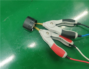
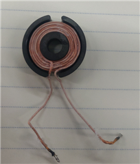
The inductance is a ferrite wire wound inductor with a diameter of 26mm. The maximum sensing distance is 15mm. L: 70uH; C: 1000pF

There are several problems in the use process:
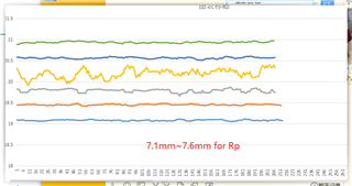
Q1: Everything is normal at a short distance (<8mm), but when moving at a long distance (>10mm), Rp is very unstable. Can this be improved? I noticed that you always recommend PCB coils,Is this the key?
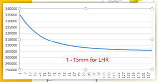
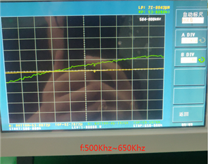
Q2: Aiming at the problem of Q1, Therefore, the long-distance test adopts the LHR mode for measurement. The curve of the exported data is very good. but when debugging the second PCB (the other 69uH induction), Large deviations in LHR data. But the Rp changes of the two PCBs are very close, i think that the PCB and the inductance are good. How to explain it? Is there a formula to derive the relationship between distance and L?
help please..
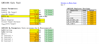
Do I need to attach the configuration of the program?

  • Hello, 

    1. What is the Rp of the sensor you are using while in free spaced (no target)?

    2. The distance also depends on the coil size so there isn't a direct relationship from L, but you should be getting a similar curve to what you showed for both coils with a slight offset between them due to the inductance difference. Is this the case or is the 69uH inductor showing completely different results? 

    Thank you, 

    Justin Beigel

  • A1:56KΩ

    A2:the 69uH inductor showing completely different results

    Ps:The inductance is a ferrite wire wound inductor

  • Thank you for the additional information. There are a few things I would like to double check.

    • Can you share the configuration for the device?
    • Can you share a screen capture of the 69uH inductor data?
    • If you measure the Rp vs frequency of the two different coils using a network analyzer, do they have the same curve? 

    Best Regards, 

    Justin Beigel

  • A1: ldc1101App.zip

    A2:no data,when found that the LHR data was unavailable, the test record was not continued.

    A3:two inductor  close and same

  • Thank you for the additional information. 

    In the configuration files you sent, it looks like the Rp max is currently set to 48kOhm with the option to switch to 96kOhms. Just want to make sure that this is set to 96kOhms in your script. 

    To clarify on the network analyzer measurement, it needs to be the LC to properly measure the Rp that the device will be measuring. If you have a way to clip into the LC that is on the board, that would be best. Additionally, another test here would be to look at the sensor oscillation on an oscilloscope. For the case where you don't have LHR data, this would be the next step. If you can provide a capture of the LC oscillation during this case, that would be helpful in understanding why you don't have data. 

    Also, I did want to mention that there will be a limit to how accurate the Rp measurement can be as you get farther away from the coil. Similar to the LHR data you showed, the change in Rp decreases as the target gets farther away from the coil. Sine 10mm is 2/3rd of your 15mm inductor, the Rp measurement might not be able to be improved much. We have a graph in the datasheet showing this relationship (figure 49) but it stops at 55% of the coil diameter. 

    Best Regards, 

    Justin Beigel

  • The configuration is older and maybe i change it , it’s okay.

    emmm.i have no time debug this anymore, i will try turn to ldc1051 or ldc1041, the lower f maybe fix my problem.

    my sensor work in -40℃~+85℃,so  Temperature compensation strategies? can i use snaa212a ? α is what,Cu 1.75 ×10⁻⁸

    The inductance is a ferrite wire wound inductor

  • Hello, 

    For temperature compensation, yes you can use the snaa212a.pdf app note. You should also make sure you are using a C0G/NP0 grade capacitor to minimize the effects of temperature. 

    Lastly, you can also use a second coil as a reference for temperature compensation. The second coil would not interact with a target and it's data would only change with temperature. 

    Best Regards, 

    Justin Beigel

  • LDC1051,it doesn't match ,which one is ture .

    and D43, D45 is what ?

  • Hello, 

    The datasheet calculation has a typo. The calculation for Y should be Proximity Data/Max Code. Since this is 8 bit data rather than 7 bit, max code should be 255 rather than 2^7. The calculation shown uses 50 decimal so if you redo the datasheet calculation with either 255 or 2^8, you should get the same answer as the calculation tool. 

    D43 and D45 are just intermediate calculation steps for this that aren't shown. 

    Best Regards, 

    Justin Beigel