This thread has been locked.

If you have a related question, please click the "Ask a related question" button in the top right corner. The newly created question will be automatically linked to this question.

LDC1051: Selecting an appropriate LDC

Part Number: LDC1051
Other Parts Discussed in Thread: LDC1614

Hello all,

I am interested in building a data aquisition circuit for a sensor I have been developing in which a signal is generated from a change of inductance (~1-5 nH) based off of a physical input. I was wondering if either the LDC 1051 / LDC1614 would be appropriately sensitive for this application? If not, could you recommend an alternative?

Thank you in advance for all your help!


  • Michael,

    I think this will partly depend on the sensor inductance as well.  For example, LDC1614 has a sensor frequency range of 1 kHz to 10 MHz.  Assuming a capacitance of 1 nF, then the sensor inductance could be as low as about 250 nH.  With this inductance, a shift like you describe would produce a variation in resonant frequency of about 20-100 kHz.  However, with a larger inductor like 5 uH, then this range of variation changes to 200 Hz - 1 kHz.  

    I would recommend that you start by using the Inductive Sensing Design Calculator Tool to help evaluate your system and LDC device.

    Additionally, these guides provide some additional guidance working with these devices

    https://www.ti.com/lit/ug/tiducr1/tiducr1.pdf - LDC1614 touch button reference design (measures 0.28 um deflection)

    https://www.ti.com/lit/an/snoa954d/snoa954d.pdf - LDC device selection guide

    https://www.ti.com/lit/an/snoa957b/snoa957b.pdf - Target design guide

    https://www.ti.com/lit/an/snaa221b/snaa221b.pdf - Rp Conditions and requirements for LDC devices

    LDC1614 offers 28 bits of resolution, so I would expect that it is very likely you should be able to create a working setup using this device.  It will be important to ensure that you meet the various requirements as described in these documents in order to achieve the best quality output signal.

    Thanks,

    Scott

  • Hi Scott,

    Thanks for the reply! The sensors have an inductance of around 80-200 nH depending on the design, with an optimal sensing frequency of around 250 to 500 kHz (not the resonance frequency, but shows the largest inductance change due to the physical forces which driving the signal change). I am hoping to use these LDCs to resolve time sensitive changes of the mentioned inductance changes with a resolution of around a few or ideally sub-millisecond. Some of the documentation that you provided does not exactly match up as my sensors are 3D solenoids, though from the basic equations I do believe that there should be an fdelta of around 200 kHz. In theory, these should be able to resolve sinusoidal changes of the inductance with millisecond resolution? 

    Thanks,

    Michael

  • Michael,

    That is an interesting application. In theory, I think that this could still work. The maximum sample rate on LDC1614 is 4.08 ksps when operating in continuous mode, so it should also be able to achieve the timing requirement of < 1ms.

    Thanks,

    Scott

  • Thank you for the advice! I will order a few and see what I can manage. Are there any resources with the LDC1614 that I can use as reference maybe a .sch file of the schematics of the EVAL board? Also, as I am potentially pushing the limits of the LDC is there any value in swapping out the capacitors on the EVAL board with higher precision options?

  • Michael,

    Sure! the schematics and BOM for the EVM are located at the end of this document:

    https://www.ti.com/lit/ug/snou135a/snou135a.pdf

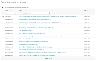
    On the product page, there is a technical documentation section with more materials you can use:

    https://www.ti.com/product/LDC1614

    It looks like the BOM indicates that the capacitors are 5%, so there may be some value in swapping these out during your evaluation of your solenoid if you're looking to keep operating points tight.

    Thanks,

    Sctt