This thread has been locked.

If you have a related question, please click the "Ask a related question" button in the top right corner. The newly created question will be automatically linked to this question.

IWR6843ISK: extremely fast range measurement

Part Number: IWR6843ISK
Other Parts Discussed in Thread: IWR6843,

Hi there,

We are developing a project based on IWR6843ISK. The aim is simply measuring the range between a moving object and the radar device. However, the working condition is somehow special compared to those common ones. Let's say the object is rotating extraordinarily fast at around 800rpm and the shape of it is quite thin (the width around 30cm) causing the time interval during which the shortest range between the object and the radar can be measured is shorter than 1ms (around 0.7ms according to the calculation). Every single frame should last less than this time interval so that every time the object sweeps across the radar, the measurement can be carried out at least once. Other radar data processing procedures like doppler or aoa estimation are not necessary. Is it ever possible to do such a fast measurement using IWR6843? Or any advice regarding the description above?

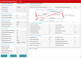
This is the result using mmWaveSensingEstimator.

thx

Shen

  • Hi Shen,

    Could you re-send the result using the Sensing Estimator?  The image did not attach properly and I cannot view it.

    One way to handle objects that exceed max velocity is by using a chirp that meets the max velocity detection required. There is a reference implementation mentioned in https://e2e.ti.com/support/sensors-group/sensors/f/sensors-forum/684385/mmwave-sensors-chinese-remainder-theorem-in-the-fmcw-radars. Also you can refer to TI design https://www.ti.com/tool/TIDEP-0092 for more details on the implementation. Although the TI design is for a different device the same concepts can be adopted to IWR6843ISK devices as well. 

    Regards,

    Brennan

  • Hi Brennan,

    Thanks for your reply. Here I attach the results from the sensing estimator. Hope it shows up properly this time. Meanwhile I will head to the reference you mentioned. Since we don't need to measure the velocity, it should work even though the object is moving at a velocity exceeding the max measureable one of the 6843. Besides, the radial velocity is quite low, since its rotating instead of approaching or leaving the radar. As long as the range FFT is performed in parallel to the ADC process or simply fast enough during the inter-chirp period, our aim can be achieved.  If there is any problem with these thoughts or regarding the estimating results, please let me know. 

    Thanks & regards

    Shen

  • Shen,

    This all looks fine to me.  Please let me know if you experience any additional issues.

    Regards,

    Brennan

  • Brennan,

    We spent couple of days digging into the source code of the high accuracy level sensing demo included in mmwave industial tool box, since we think it might be more efficient to achieve our goal by modifying the code a bit to meet our demands. However there are a few problems that make us confused. Maybe you could give us some hints.

    1. Not sure what the mailbox exactlly is. Does it also use a UART interface?

    2. We've noticed baud rate is set both in dss main.c and mss main.c respectively. The baud rate set in mss, according to our understanding, is used in comminication with external devices like the gui host machine. So what is the baud rate set in dss for? Is it necessary to force these two to be the same?

    3. We modified the Cfg file that configures parameters like frame period, number of chirps per frame, etc. When we set the parameters according to the results given by the estimator, like #chirps per frame is 1 and frame period is 1ms, no data can be recieved. There must be sth that we have missed. What could it be?

    4. Could you point out in which part the Cfg file is parsed by which API? It is read first by the mss and then sent to dss via mailbox? Does it have anything to do with the CLI module?

    The offcial documents might have answers to these questions, but you know those hundreds of pages are sometimes like a huge maze. Really appreciate it if you could make things clear for us.

    Regards,

    Shen

  • Hi Shen

    1) Please see Section 18 of the Technical Reference Manual for information on the Mailbox mechanism in the IWR device.

    2) Previously, this demo had the ability to choose whether the MSS or DSS would output the data to UART.  However, this is not the case anymore and only the MSS outputs data to UART.  You can ignore the baud rate settings in the DSS.  

    3) Please ensure that all the necessary parameters are set and that they are within the bounds of the acceptable values for each parameter.  Go through the SDK User's Guide, starting on page 19 and check your parameters and values.

    4) Could you be more specific in this question?  Please see section 5 of the SDK User's Guide and let me know if you need more information.

    Regards,

    Brennan