This thread has been locked.
If you have a related question, please click the "Ask a related question" button in the top right corner. The newly created question will be automatically linked to this question.
Hi,
I was trying to collect some raw ADC data by using Studio CLI, because it is a quicker way compared with going through steps on mmwave studio.
However, I found I was not able to collect valid raw ADC data by using Studio CLI with IWR1642Boost and DCA1000EVM even with the default cfg file.
(1) The setup is as follows.
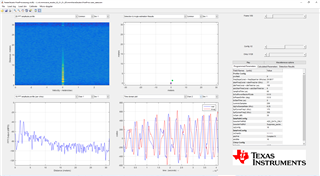
(2) First, I want to make sure the hardware are working. I used mmwave studio for testing. It can detect the strong reflector.
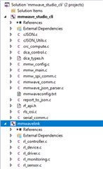
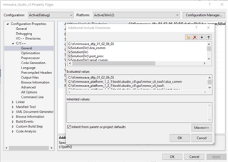
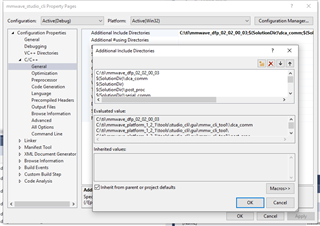
(3) Then, I first flashed mmwave_Studio_cli_xwr16xx.bin for using Studio CLI.
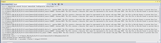
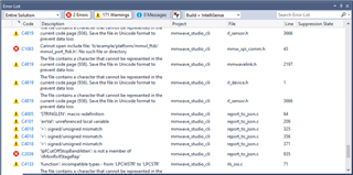
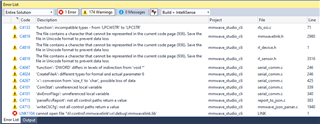
(4) In the mmwaveconfig.txt file, I first used MMWAVE_DEVICE_VARIANT=IWR1642, it gave me error as below.
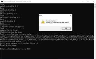
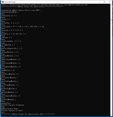
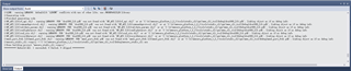
(5) Then, I changed MMWAVE_DEVICE_VARIANT=AWR1642. However, the program stuck as below.
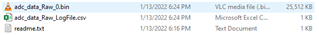
I double check the collected data. The size was wrong. It should be 4 * 256 * 32 * 2 * 4 * 100 = 25600 KB
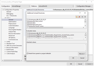
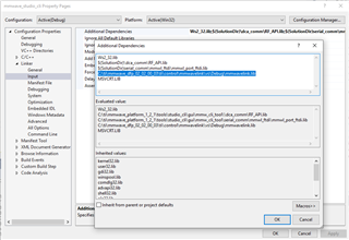
I also attached the mmwaveconfig.txt and profile_monitor_xwr16xx.cfg. I used default settings for both of them.
# # Refer Developer's User Guide document for usage details # ########## CAUTION: Don't change any variable name in this file. ########## # # mmWave Device Variant # AWR1443, AWR1642, AWR1843, AWR6843, AWR1243, AWR2243 # IWR1443, IWR1642, IWR1843, IWR6843 # For AWR1243 and AWR2243 device This tool uses SPI interface and uses JSON file for configuration input # For other devices it uses UART COM port and can use CFG or JSON input file. # # @Note: For AWR1243/AWR2243 # a. If FW_DOWNLOAD_ENABLE=1 & FLASH_CONNECTED_TO_SENSOR=1 # then: Flash matching MetaImage binary file to device first. # b. Set LVDS Lanes (DCA_LVDS_LANE_MODE=4) # MMWAVE_DEVICE_VARIANT=AWR1642 # # COM port number (@921600 baud rate) # Same COM port is being used for sending CLI commands # And after sensorStart same COM port is used to read monitoring data. # COM_PORT_NUM=13 # # Global configuration: these define the task to be done # # To configure the mmWave RF Front End : [ENABLE_CONFIG_MMWAVE] 1-Yes, 0-No # To capture Monitoring report to JSON file : [ENABLE_MONITOR_CAPTURE] 1-Yes, 0-No # To capture Raw ADC data using DCA1000 : [ENABLE_DCA_CAPTURE] 1-Yes, 0-No # To post process the captured ADC data : [ENABLE_POSTPROC] 1-Yes, 0-No, assuming postproc.exe is available at same path of this tool # mmWave Config file can be *.cfg or JSON format : [CONFIG_FILE_FORMAT] 1-cfg, 0-json # ENABLE_CONFIG_MMWAVE=1 ENABLE_MONITOR_CAPTURE=1 ENABLE_DCA_CAPTURE=1 ENABLE_POSTPROC=1 CONFIG_FILE_FORMAT=1 # # Path for mmWave Config JSON or .cfg file (including file name). # JSON file must be generated by SensingEstimator or mmWave Studio # Set CONFIG_FILE_FORMAT accordingly. # CONFIG_JSON_CFG_PATH=..\cfg_xWR1642\profile_monitor_xwr16xx.cfg # # Path to store the monitoring report in JSON format # Each report in seperate JSON file # Note: make sure this path and directory exist # MONITORING_JSON_PATH=..\monitor_report_dir # # Number of monitoring report to store in JSON file # Set to zero for infinite time till terminated (CLI CMD: "quit") or CLI CMD : "monCaptureStop" # NUMBER_OF_MONITOR_REPORT_STORE=10000 # # Path to store Captured ADC data binary file # CAPTURED_ADC_DATA_PATH=..\captured_adc_xWR1642 # # DCA1000 Configurations # It captures the number of frames worth data which is given in JSON or CFG file # # DCA_FILE_PREFIX: File prefix for each ADC data DCA1000 captures. # e.g. with ‘adc_data’ prefix, file name would be adc_data_Raw_0.bin # # DCA_MAX_REC_FILE_SIZE_MB: Max size of each ADC data file DCA1000 captures, at this size limit it splits captured data into next binary file. # # DCA_DATA_FORMAT_MODE: 1: 12Bit, 2: 14Bit, 3: 16Bit mode # # @Note make sure this format matches with data-format in CFG or JSON config parameters. # DCA_LVDS_LANE_MODE: 2 or 4 LVDS lanes (AR1243/2243 - 4 lane, AR1642/1843/6843 - 2 lane) # DCA_FILE_PREFIX=adc_data DCA_MAX_REC_FILE_SIZE_MB=100 DCA_DATA_FORMAT_MODE=3 DCA_LVDS_LANE_MODE=2 # # PostProc exe utility path # This tool is provided along with CLI tool, so you may not touch this input text # POST_PROC_EXE_PATH=..\mmw_post_proc\mmwave_postproc.exe # # Set this parameter when you need to run this CLI tool with CCS image running # i.e. Not running from Flashed App-Image but loading application from CCS. # In that case application sometime responses slowely for CLI CMD so in the # tool we will add delay for each CLI CMD so it doesn't get expire with error. # 0: Running from Flash, 1: running from CCS # CCS_DEBUG=0 # # Below Configuration is mainly used for AWR1243/AWR2243 device # When Communication happens over SPI interface using mmwavelink library # # # If Firmware Download is disabled with AWR1243/AWR2243 device # 0: Yes, 1: No firmware download # For this tool, it is recommended to flash the firmware and set this option to '1' # As this tool doesn't contains all version of FW for AWR1243/AWR2243. # FW_DOWNLOAD_DISABLE=1 # # If sFlash is connected with AWR1243/AWR2243 device # 1: Yes, 0: nosFlash is connected with sensor # FLASH_CONNECTED_TO_SENSOR=1 # # power on master arguments, please modify if needed (for AWR1243/AWR2243) # rlClientCbs_t: CRC_TYPE 0: 16Bit, 1: 32Bit, 2: 64Bit # ACK_TIMEOUT : ACK Timeout for mmWaveLink # CRC_TYPE=1; ACK_TIMEOUT=5000; # # End of Config File #
It seems Studio CLI does not support IWR1642 with DCA1000EVM well? Any suggestions?
Thank you very much!
Best,
Hang
Hello,
After several tries, I think the main problem is that the captured data was always less than the theoretical calculated size (even with the default settings in mmwaveconfig.txt and profile_monitor_xwr16xx.cfg provided above).
However, when use mmwave studio, I didn't have such issue.
From the picture below, it seems the DCA1000EVM was triggered after sensorStart. However, I didn't not modify anything. The file mmwaveconfig.txt is attached.
# # Refer Developer's User Guide document for usage details # ########## CAUTION: Don't change any variable name in this file. ########## # ------------------------------------------------------------------------- # mmWave Device Variant # AWR1443, AWR1642, AWR1843, AWR6843, AWR1243, AWR2243 # IWR1443, IWR1642, IWR1843, IWR6843 # For AWR1243 and AWR2243 device This tool uses SPI interface and uses JSON file for configuration input # For other devices it uses UART COM port and can use CFG or JSON input file. # # @Note: For AWR1243/AWR2243 # a. If FW_DOWNLOAD_ENABLE=1 & FLASH_CONNECTED_TO_SENSOR=1 # then: Flash matching MetaImage binary file to device first. # b. Set LVDS Lanes (DCA_LVDS_LANE_MODE=4) # ------------------------------------------------------------------------- MMWAVE_DEVICE_VARIANT=AWR1642 # ------------------------------------------------------------------------- # COM port number (@921600 baud rate) # Same COM port is being used for sending CLI commands # And after sensorStart same COM port is used to read monitoring data. # ------------------------------------------------------------------------- COM_PORT_NUM=13 # ------------------------------------------------------------------------- # Global configuration: these define the task to be done # # To configure the mmWave RF Front End : [ENABLE_CONFIG_MMWAVE] 1-Yes, 0-No # To capture Monitoring report to JSON file : [ENABLE_MONITOR_CAPTURE] 1-Yes, 0-No # To capture Raw ADC data using DCA1000 : [ENABLE_DCA_CAPTURE] 1-Yes, 0-No # To post process the captured ADC data : [ENABLE_POSTPROC] 1-Yes, 0-No, assuming postproc.exe is at same path of this tool # mmWave Config file can be *.cfg or JSON format : [CONFIG_FILE_FORMAT] 1-cfg, 0-json # ------------------------------------------------------------------------- ENABLE_CONFIG_MMWAVE=1 ENABLE_MONITOR_CAPTURE=0 ENABLE_DCA_CAPTURE=1 ENABLE_POSTPROC=0 CONFIG_FILE_FORMAT=1 # ------------------------------------------------------------------------- # Path for mmWave Config JSON or .cfg file (including file name). # JSON file must be generated by SensingEstimator or mmWave Studio # Set CONFIG_FILE_FORMAT accordingly. # ------------------------------------------------------------------------- CONFIG_JSON_CFG_PATH=..\cfg_xWR1642\profile_monitor_xwr16xx.cfg #CONFIG_JSON_CFG_PATH=..\cfg_xWR1642\profile_2_4.cfg # ------------------------------------------------------------------------- # Path to store the monitoring report in JSON format # Each report in seperate JSON file # Note: make sure this path and directory exist # ------------------------------------------------------------------------- MONITORING_JSON_PATH=..\monitor_report_dir # ------------------------------------------------------------------------- # Number of monitoring report to store in JSON file # Set to zero for infinite time till terminated (CLI CMD: "quit") or CLI CMD : "monCaptureStop" # ------------------------------------------------------------------------- NUMBER_OF_MONITOR_REPORT_STORE=10000 # ------------------------------------------------------------------------- # Path to store Captured ADC data binary file # ------------------------------------------------------------------------- CAPTURED_ADC_DATA_PATH=..\captured_adc_xWR1642 # ------------------------------------------------------------------------- # DCA1000 Configurations # It captures the number of frames worth data which is given in JSON or CFG file # # DCA_FILE_PREFIX: File prefix for each ADC data DCA1000 captures. # e.g. with ‘adc_data’ prefix, file name would be adc_data_Raw_0.bin # # DCA_MAX_REC_FILE_SIZE_MB: Max size of each ADC data file DCA1000 captures, at this size limit it splits captured data into next binary file. # # DCA_DATA_FORMAT_MODE: 1: 12Bit, 2: 14Bit, 3: 16Bit mode # # @Note make sure this format matches with data-format in CFG or JSON config parameters. # DCA_LVDS_LANE_MODE: 2 or 4 LVDS lanes (AR1243/2243 - 4 lane, AR1642/1843/6843 - 2 lane) # ------------------------------------------------------------------------- DCA_FILE_PREFIX=adc_data DCA_MAX_REC_FILE_SIZE_MB=100 DCA_DATA_FORMAT_MODE=3 DCA_LVDS_LANE_MODE=2 # ------------------------------------------------------------------------- # PostProc exe utility path # This tool is provided along with CLI tool, so you may not touch this input text # ------------------------------------------------------------------------- POST_PROC_EXE_PATH=..\mmw_post_proc\mmwave_postproc.exe # ------------------------------------------------------------------------- # Set this parameter when you need to run this CLI tool with CCS image running # i.e. Not running from Flashed App-Image but loading application from CCS. # In that case application sometime responses slowely for CLI CMD so in the # tool we will add delay for each CLI CMD so it doesn't get expire with error. # 0: Running from Flash, 1: running from CCS # ------------------------------------------------------------------------- CCS_DEBUG=0 # ------------------------------------------------------------------------- # Below Configuration is mainly used for AWR1243/AWR2243 device # When Communication happens over SPI interface using mmwavelink library # ------------------------------------------------------------------------- # ------------------------------------------------------------------------- # If Firmware Download is disabled with AWR1243/AWR2243 device # 0: Yes, 1: No firmware download # For this tool, it is recommended to flash the firmware and set this option to '1' # As this tool doesn't contains all version of FW for AWR1243/AWR2243. # ------------------------------------------------------------------------- FW_DOWNLOAD_DISABLE=1 # ------------------------------------------------------------------------- # If sFlash is connected with AWR1243/AWR2243 device # 1: Yes, 0: nosFlash is connected with sensor # ------------------------------------------------------------------------- FLASH_CONNECTED_TO_SENSOR=1 # ------------------------------------------------------------------------- # power on master arguments, please modify if needed (for AWR1243/AWR2243) # rlClientCbs_t: CRC_TYPE 0: 16Bit, 1: 32Bit, 2: 64Bit # ACK_TIMEOUT : ACK Timeout for mmWaveLink # ------------------------------------------------------------------------- CRC_TYPE=1; ACK_TIMEOUT=5000; # # End of Config File #
Thank you very much for the help!
Best,
Hang
Hi Hang,
This is known issue post last release, and fix will be available in the upcoming release
You need to rebuild the mmw_cli_tool.exe with below code change using Visual Studio project (mmwave_studio_cli.sln)
Regards,
Jitendra
Hi Jitendra,
Thank you very much!
Is there any tutorial for rebuilding mmw_cli_tool.exe?
I found these two posts, AWR1843: mmWave Studio CLI Tool cannot be started and AWR1843: Unable to rebuild the visual studio solution for studio CLI tool
However, I still got some error when I tried to rebuild it. I used C:\ti\mmwave_dfp_02_02_03_01.
Should I use Visual Studio 2017 (x86) or Visual Studio 2017 (x64)?
Please let me summarize my steps here:
(1) I install visual studio 2017 (x86) and mmwave_dfp_02_02_03_01.
(2) Under C:\ti\mmwave_platform_1_2_1\tools\studio_cli\gui\mmw_cli_tool, I double clicked mmwave_studio_cli.sln
(3) I added mmwave_dfp_02_02_03_01 path to mmwave_studio_cli as below.
(4) I added C:\ti\mmwave_dfp_02_02_03_01\ti\control\mmwavelink\vs\mmwavelink.vcxproj to mmwave_studio_cli.sln as suggested in previous post.
(5) I can successfully rebuild mmwavelink as below.
(6) Then, I tried to rebuild mmwave_studio_cli. I still got 4 errors as below.
Thank you very much for the help!
Best,
Hang
Hi Hang,
Please install this DFP (01.02.06.03) and use path from this.
https://www.ti.com/tool/download/MMWAVE-DFP
Regards,
Jitendra
Hi Jitendra,
Thanks! However, it still didn't work and I got two errors as below.
From this post AWR1843: mmWave Studio CLI Tool cannot be started, you were suggesting mmwave_dfp_02_02_03_01. Is there a specific reason for going back an older version of dfp? Which version of mmwave_platform you were using?
Thank you very much for the help!
Best,
Hang
Sorry about that confusion.
Default Studio CLI supports AWR2243 ES1.0 and built with mmwave_dfp_02_02_00_01
With this path include you should able to rebuild the project.
Regards,
Jitendra
Hi Jitendra,
Thanks! However, the oldest version I can find online to download is mmwave_dfp_02_02_00_03.
It sill gave me one error as below, "cannot open file "\ti\control\mmwavelink\vs\debug\mmwavelink.lib"
I tried to include C:\ti\mmwave_dfp_02_02_03_01\ti\control\mmwavelink\vs\mmwavelink.vcxproj to mmwave_studio_cli.sln and rebuilt it.
I also tried to include C:\ti\mmwave_dfp_02_02_00_03\ti\control\mmwavelink\vs\mmwavelink.vcxproj to mmwave_studio_cli.sln and rebuilt it.
Both above didn't work on my side.
Could you share me the link for downloading mmwave_dfp_02_02_00_01?
Thanks!
Best,
Hang
First check if you have mmwavelink.lib fie at C:\ti\mmwave_dfp_02_02_03_01\ti\control\mmwavelink\vs\Debug
and include the full path of this library in the project property.
I don't find 2.2.0.1 but above version should work.
Hello Jitendra,
Thanks for the suggestion.
I was able to successfully compile the code and generate mmwave_studio_cli.exe under C:\ti\mmwave_platform_1_2_1\tools\studio_cli\gui\mmw_cli_tool\Debug.
However, the new executable file mmwave_studio_cli.exe still can not capture the right amount of data.
Here are what I did.
(1) I change the path of mmwavelink.lib in Linker -> Input as below. Then, I can successfully compile the code.
(2) I used the new generated executable for capturing raw ADC data.
It did better job than before, the old one can only capture 25344KB, the new one can capture 25512KB. However, neither of them is correct.
From the default chirp/frame settings. The right amount of data should be 4 * 256 * 2 * 4 * 32 * 100 = 25600 KB
(3) The only part of code I changed in mmw_main.c is as below. I also tried delay 2 second. It didn't help.
Any suggestions? Thank you very much!
Best,
Hang
that is very unlikely to capture wrong amount of data with this fix.
I need to try this on my next working day to confirm this issue at my end. (today is holiday in India).
Meanwhile you can use mmwave studio GUI to proceed with your experiment.
Hi Jitendra,
Thank you so much! I listed what I used here.
(1) VS2017 (x86)
(2) mmwave_platform_1_2_1, modified the code in mmw_main.c
(3) mmwave_dfp_02_02_00_03, include path and add C:\ti\mmwave_dfp_02_02_00_03\ti\control\mmwavelink\vs\mmwavelink.vcxproj to C:\ti\mmwave_platform_1_2_1\tools\studio_cli\gui\mmw_cli_tool\mmwave_studio_cli.sln
(4) Modify input path of mmwavelink.lib for C:\ti\mmwave_platform_1_2_1\tools\studio_cli\gui\mmw_cli_tool\mmwave_studio_cli.sln
Thanks!
Best,
Hang
Hi,
I have forwarded this issue to internal team to investigate and if find fix in upcoming version.
Meanwhile you can either use mmwave studio or dca1000 cli tool (within mmwave studio installation) or just ignore one/few frame data captured using current studio cli tool.
Regards,
Jitendra
Hi Jitendra,
Thanks!
For ignoring one/few frame data captured, you know how to truncate the data? From the head or tail of the bin file?
Thank you very much!
Best,
Hang
Hi Hang,
You need to find out which part it is not able to capture (head/tail). Using PostProc tool you can check this, if while scrolling to last few frame it gives any error in the console.
So effectively while processing the data you can skip those number of frames (compare to number of frames requested for capture).
Regards,
Jitendra
Hi Jitendra,
Thank you very much! However, I don't quite understand this "Using PostProc tool you can check this, if while scrolling to last few frame it gives any error in the console."
For my testing, I intended to collect 100 frames with 256 KB for each frame. I collected 25512 KB as a result.
25344 KB < 25512 KB < 25600 KB
This means I collected 99 complete frames and there are 168 KB (25512 KB - 25344 KB) should be discarded either from head or tail.
I enabled PostProc (ENABLE_POSTPROC=1) and run mmwave_studio_cli.exe.
However, the mmwave_postproc.exe was not able to run. "AWR1642Could not access the MATLAB runtime component cache."
So what do you mean by "Using PostProc tool you can check this, if while scrolling to last few frame it gives any error in the console."
Thank you very much for the help!
Best,
Hang
Hi Hang,
This error for postProc is connected with Matlab runtime, please refer user guide to install the correct version of Matlab Runtime (which is required to run the PostProc tool).
When you will able to open the PostProc tool, there you can see frame count slider which you can slide for specific frame number and if ignore that specific frame which is not captured by the tool.
Regards,
Jitendra