This thread has been locked.
If you have a related question, please click the "Ask a related question" button in the top right corner. The newly created question will be automatically linked to this question.
Hi,
I have a question on how to collect raw ADC data with beam steering configuration.
I have read the MRR Beam Steering lab from here. On page 5, it has configuration as below.
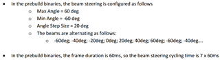
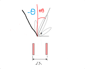
The radar was configured to scan from -60 degrees to 60 degrees with step size of 20 degrees. In this case, the beam steering cycle is 7, namely [-60deg, -40deg, -20deg, 0deg, 20deg, 40deg, 60deg]
From this post, I understand that all TXs were triggered simultaneously.
In my case, I use IWR1642Boost, two TXs of IWR1642Boost should be configured with different phase shift values for [-60deg, -40deg, -20deg, 0deg, 20deg, 40deg, 60deg], respectively.
Is there reference I can refer for such configurations?
For example, how to configure these two TXs with beam steering at - 60deg on mmwave studio?
Thanks a lot for the hints!
Best,
Hang
Hi
xWR1642 does not support the hw phase shifters required for beam steering.
You need to use xWR1843
Thank you
Cesar
Hi Cesar,
Thanks!
I also have a AWR1843Boost.
If I just want to use the two horizontal antennas of AWR1843Boost & DCA1000EVM for raw data capturing with beam steering (at [-60deg, -40deg, -20deg, 0deg, 20deg, 40deg, 60deg])
Could you give me some hints?
Thanks!
Best,
Hang
HI, Hang:
You can refer to the document at https://dev.ti.com/tirex/explore/node?node=ADB-lBeMHspqQq8ks4cGHg__VLyFKFf__LATEST to understand how to program the phase rotator to achieve different steering angle.
Best,
Zigang
Hi Zigang,
Thanks a lot for the hints! Please give me few days to study it.
Best,
Hang
Hi Zigang,
I have studied the document and I have quick question.
From this post, I found the definition of theta is different. Which one is correct?
To set the phase shift values on TX0, TX1, and TX2 on AWR1843Boost,
ar1.SetPerChirpPhaseShifterConfig(0, 0, TX0_val, TX1_val, TX2_val)
If I only wants to use TX0_val and TX2_val (azimuth) antennas, what values I should use for beam steering -30 and +30 ?
I found TX0_val and TX2_val have to be UInt16 for ar1.SetPerChirpPhaseShifterConfig() commands.
I understand the equation on the document. I don't know how to set values for negative beam steering angle.
NTX = 2;
d = 2 * lamda; % space between TX0 and TX2
for i = 1:NTX
txPhase(1, i) = rad2deg( (i-1)*(2*pi*d/lamda)*sin(deg2rad(theta)) );
end
Thanks a lot!
Best,
Hang
HI, Hang:
You should be able to find the reference code for phase calculation at the end of this document. For xwr1642, only TX0/TX1 are available, you can program everything the same, but just enable only TX0 and TX2 in the chirp configuration. And then you can modify theta_desired as the desired steering angle. For the nagative phase, you will need to wrapTo360 to make it positive.
theta_desired = -33.75;
m_ind = [0 2]; % antenna distance in unit of lambda
phaseInc = 5.625; % step size for the phase shifter
phaseTX_rad = 2*pi*(m_ind*sind(theta_desired));
phaseTX_deg = (phaseTX_rad)*180/pi;
phaseTX_deg_wrap = wrapTo360(phaseTX_deg);
If you are use rlRfSetPhaseShiftConfig API, then you can the check the Doxygen Documentation below for programming. and file:///C:/ti/mmwave_sdk_03_05_00_04/packages/ti/control/mmwavelink/docs/doxygen/html/structrl_rf_phase_shift_cfg__t.html
Best,
Zigang
Hi Zigang,
My bad! Thanks a lot!
Just to verify the positive and negative theta_desired is shown as the picture below.
From my understanding, by using beam steering at a desired angle, the maximum range will be increased.
Is there any reference from TI for the calculation of this increased maximum range? Or it is based on experiments?
Thanks!
Best,
Hang
Sorry, I still got another question. From the document, file:///C:/ti/mmwave_sdk_03_05_00_04/packages/ti/control/mmwavelink/docs/doxygen/html/structrl_rf_phase_shift_cfg__t.html
tx0PhaseShift: 0 to 63
tx1PhaseShift: 0 to 63
tx2PhaseShift: 0 to 63
% [-60, -40, -20, 0, 20, 40, 60]
% [0 17], [0 46], [0 20] [0 0], [0 44], [0 18], [0 47]
theta_des = 60;
m_ind = [0 2];
phaseInc = 5.625;
phaseTX_rad = 2*pi*(m_ind*sind(theta_des));
phaseTX_deg = (phaseTX_rad)*180/pi;
phaseTX_deg_wrap = wrapTo360(phaseTX_deg);
phaseTX_bit = round(phaseTX_deg_wrap/phaseInc);
From my calculate, the steering angle at -40 and +60, result in very close value, namely [0 46] and [0 47]
How could the system distinguish them? Since the beam steering angles are very different.
Thanks!
Best,
Hang
Hi, Hang:
Theoretically, the TX beamforming can increase the antenna gain up to 20*log10(Nant). Where Nant is the number of TX antenna that are used for TX beamforming. You can then calculate the maximum range increase at the bore sight direction. For Nant = 3, you can expect a maximum detectable range increase by 70%.
Best,
Zigang
Hi, Hang:
When you steering the beam to a desired angle, it also have side lobe (same gain as the main lobe). So, -40 and 60 happens to be close to each other's side lobe.
Best,
Zigang