This thread has been locked.

If you have a related question, please click the "Ask a related question" button in the top right corner. The newly created question will be automatically linked to this question.

DRV5053RA problem

Other Parts Discussed in Thread: DRV5053

Hi,

I have a problem on a card with a card on debugging test.

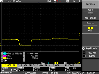
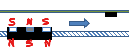
Usually, it goes 0V or 2V depending magnetization. This one goes 0V or 1.22V (see screenshot below).

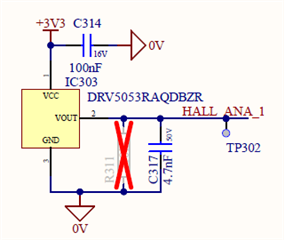
Supply is 3.3V and don’t move then toggled, decoupling capacitor has been changed without modification.


Card becomes OK then component has been changed. Old component can be send for analysing.

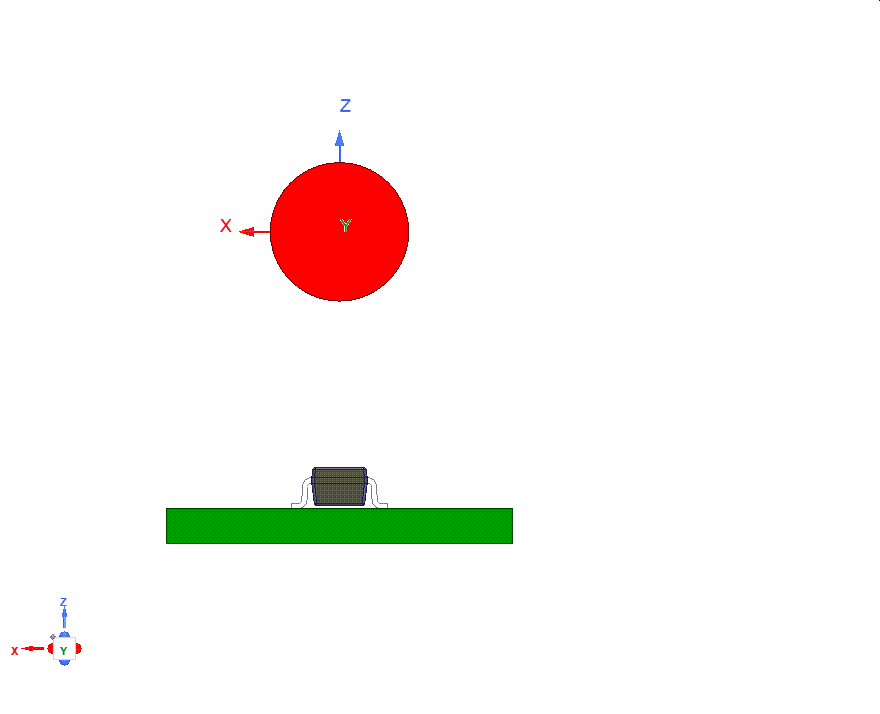
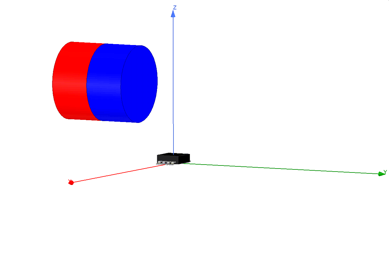
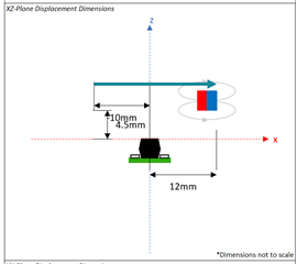
Component is close to piece moving (position sensing), is chocks can make this behaviour ?

The system is near to be in serial production, we need to understand what is happen.

Thanks,

  • Hi Thibault,

    Can you provide a video that shows the issue?  Also, can you provide information on the magnet (strength, shape, dimensions) and the distances from the magnet to the sensor?

    In addition, can you bring the south pole of an external magnet near the top of the hall sensor package and tell me the output voltage you observe?  Can you also try the opposite pole of the magnet and tell me the output voltage you observe?

    Thank you,

    Mekre

  • Hi Mekre,

    The signal seen on the screenshot attached is the same magnet on one position then the opposite.

    Tested with ECLIPSE N801RS (Radiospares 695-0169), 10 pieces in a plastic box to avoid contact.

    The system usually works fine, once IC remplaced, card is OK..

    Thanks,

  • Hi Thibault,

    Can you also tell me the following:

    • For the devices that fail this test, are you saying that you are not able to see the outputs of these devices go above 1.22 V even when you apply the north pole of the magnet directly on top of the devices?
    • Can you provide a diagram that shows the magnet, its distance with respect to the sensor, and how the magnet moves with respect to the sensor?
    • Is the DRV5053 output connected to an ADC or does it drive a circuit? Can you provide a schematic snippet of the DRV5053 circuit? 
    • What percentage of your units see this issue?

    Thank you,

    Mekre

  • Hi Mekre,

    My replies below :

    • For the devices that fail this test, are you saying that you are not able to see the outputs of these devices go above 1.22 V even when you apply the north pole of the magnet directly on top of the devices? 

    Only one side doesnot work anymore. Device has been removed from board, I dont know if norh or south is affected.

    • Can you provide a diagram that shows the magnet, its distance with respect to the sensor, and how the magnet moves with respect to the sensor?

    All prototypes work ! around 50 boards has been mounted and work well.

    • Is the DRV5053 output connected to an ADC or does it drive a circuit? Can you provide a schematic snippet of the DRV5053 circuit? 

    DRV5053RA output to an ADC

    • What percentage of your units see this issue?

    Only one DRV5053 has a problem, we think vibration can be the problem. Where can I find information about it ? Can you analyse the problematic device ?

    Thank you,

  • Hi Thibault,

    These devices have not had field failures in the past, so I suspect that maybe something outside of the device has damaged it.

    Can you tell me the following:

    • Could you provide a schematic of the components around this sensor?
    • Could you also provide a diagram of how the magnet moves with respect to the device as well as the distance from the magnet to the sensor?
    • Did you notice an increase in current draw from the device that failed?

    Thank you,

    Mekre

  • Hi Mekre,

    Schematic is as below : 

    Signal goes directly to the microcontroller.

    Magnets are north-south and south-north on the top of the DRV5053, type N48, 1377-14200 G. Distance is 4.5mm.

    I don't notice any current increase after faillure.

    Regards,

  • Hi Thibault,

    Are you saying that the magnet moves similar to the below animation?

    Regards,

    Mekre

  • Hi Mekre,

    Magnets move like this : 

    White : south side up, grey : north side up

  • Hi Thibault,

    Ok, so it moves similar to the animation below.  Is this correct?

    Also, is the 4.5 mm you are referring to the 4.5 mm distance shown below or is it referring to a different distance?

    Also, what is the range of x displacements of the magnet?  In the picture above, it shows -10 mm to +12 mm as the x-displacement range, but I will need to update this with the x displacement range for your system.

    Regards,

    Mekre

  • Hi Mekre,

    Magnet magnetisation goes through the IC directly as shown :

    The 4.5mm distance is right. All the three magnets move on front od the IC.

    Regards,

  • Hi Thibault,

    If you try to install the problematic device back onto a board, do you still observe the same failure?

    Also, was the system exposed to any special EMC events, such as ESD or EFT?  Since you have a capacitor directly between the output and ground instead of using an RC filter, it is possible there could be something similar to a short during these events.

    Regards,

    Mekre