This thread has been locked.

If you have a related question, please click the "Ask a related question" button in the top right corner. The newly created question will be automatically linked to this question.

TMP1826: How to drive TMP1826?

Part Number: TMP1826
Other Parts Discussed in Thread: SN74LVC1G07

HI, All

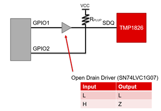
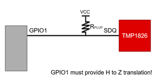
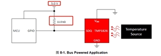
We want to drive TMP1826 with MCU GPIO,  but it can not work. we have set up it with recommended circuit from datasheet.  it is used with bus powered application.when debugging it, we have tried to adjust the pullup resistance from 330 ohm~ 11k ohm, but it still can not work. we also try to change the MCU with 3.3V type, but the result still is same.  Who can help to check it?

Below is the debug code, use CMD: ReadTemperature, ReadROM, but it only reply with 0xFF,

bit Init_DS18B20(void)
{
 bit dat=0;
 DQ = 1;    //DQ  reset
 DelayUs2x(5);   //delay
 DQ = 0;         //drive low
    Delay500us();  //   //   480us<  TMP1826 <560us
    DelayUs2x(50);   //20us
 DQ = 1;        //pullup
 Delay50us(); //15~60us
    DelayUs2x(50);   //20us
 dat=DQ;        //check DQ  
 DelayUs2x(25); //
 DelayUs2x(200);
 DelayUs2x(200);
 return dat;
}

unsigned char ReadOneChar(void)            
{
unsigned char i=0;
unsigned char dat = 0;
for (i=8;i>0;i--)
 {
  DQ = 0; //
     Delay3us()    ;
  dat>>=1;
  DQ = 1; //
     Delay20us()    ;    
  if(DQ)
    {dat|=0x80;}
    Delay50us()    ;
        DQ = 1;
    Delay20us()    ;    
 }
 return(dat);
}

void WriteOneChar(unsigned char dat)
{
 unsigned char i=0;
        DQ = 1;    
 SPower=1;
 for (i=8; i>0; i--)
 {
  if (dat&0x01)
  {    
  DQ = 0;
        Delay_5us();
  DQ = 1;
        Delay50us();
        Delay20us();
      }
      else
      {
       DQ = 0;    
            Delay20us();
            Delay50us();
            Delay20us();
          }
        
  dat>>=1;
        DQ = 1;    
            Delay20us();
 }
}

unsigned int ReadTemperatureTMP1826(void)
{
unsigned char a=0;
unsigned int b=0;
unsigned int t=0;
Init_DS18B20();
WriteOneChar(0xCC); // skip
WriteOneChar(0x44); //
Delay50ms();
Init_DS18B20();
WriteOneChar(0xCC); //
WriteOneChar(0xBE); //
a=ReadOneChar();   //low byte
b=ReadOneChar();   //high byte
Init_DS18B20();
b<<=8;
t=a+b;
return(t);
}

/*------------------------------------------------
                    Read ROM 64bit ID
------------------------------------------------*/
void ReadROM(void)
{
unsigned char i=0;
DelayUs2x(100);
Init_DS18B20();
WriteOneChar(0x33); //

  for (i=0;i<8;i++)
  {       
  BUF[i]=ReadOneChar();  
          }  
}


  • Hi Yang,

    You will need to disable the output of your GPIO in order to allow TMP1826 to respond. There are several moments where the output will need to be toggled to an "input", "Z", "tri-state" or "high impedance" state. I don't see any indication that this is happening in your code.

    thanks,

    ren

  • Hi, Ren

    Thanks for your checking.

    we test it with 8bit MCU, it does not need to configure its mode like STM32,  we can use it as output or input automatically. 

    In addition, I also tried to change the GPIO mode to “tri-state” or "high impdedance" state, but it still can not work.

    Could you share me your test code and suggested test circuit for it?

    I would appreciate it if I could.

    You will need to disable the output of your GPIO in order to allow TMP1826 to respond. There are several moments where the output will need to be toggled to an "input", "Z", "tri-state" or "high impedance" state. I don't see any indication that this is happening in your code.

  • Hi Yang,

    Here I show an extra component, the open-drain driver SN74LVC1G07, creating the Z state. This is necessary for TMP1826 to respond without contention. Since this component is one-way, you must receive on a secondary GPIO.


    To make your circuit work with one GPIO, you must instruct your GPIO to output Z instead of logic H. You do this by configuring your GPIO as an input, and reconfiguring it as an output when you need to output logic L. The IO configuration will be a separate register. It may be called an output mask. 

    // assume your controller has 8 GPIO, the 8 GPIO correspond to 8 bits
    // OUTPUT will be the 8-bit register that controls the state of the pin high/low
    // OUT_MASK will be the 8-bit register that configures the 8 pins as input or output
    
    #define SDQ 4 //this is the value of our pin in the reigster, pin 3 (hypothetical)
    
    void setSDQ(char value){
     if (value) {
      OUT_MASK &= ~SDQ; //clear bit to configure as input
      // pull-up resistor will create logic H 
     }
     else {
      OUT_MASK |= SDQ; //set bit to configure as output
      OUTPUT &= ~SDQ; //clear bit to output low
     }
    }
    
    void main(){
     setSDQ(0);
     setSDQ(1);
     setSDQ(0);
    }

    thanks,

    ren

  • Hi, Ren

    I have set it as open drain status, only connect external pull up resistance. but it still feedback 0xff.

  • Can you please show me oscilloscope capture of your SDQ activity? Are you able to see TMP1826 respond during reset pulse?

    Are you sure your controller can read input in 11 Open Drain mode as shown? Only mode 00 is described as bidirectional. Has this code worked with other devices on this controller?

    You may need to use a read delay of less than 20us. Look on scope or analyzer to confirm the actual timing. 

    thanks,

    ren

  • Hi, Ren

    Yes, I can get the respond from TMP1826 during reset pluse. below is the reset code. while DQ=1, there is 100us delay to release the bus.  you can find it has been set low by TMP1826  with 540us. it seems that it can be active.

    bit Init_DS18B20(void)
    {
     bit dat=0;
     DQ = 1;    //DQ复位
     DelayUs2x(5);   //稍做延时
     DQ = 0;         //单片机将DQ拉低
    	Delay500us();  //精确延时 大于 480us 小于960us    //   480us<  TMP1826 <560us
    //	Delay20us();   //20us
    
     DQ = 1;        //拉高总线
     Delay50us(); //15~60us 后 接收60-240us的存在脉冲
    	Delay50us();;   //20us
     dat=DQ;        //如果x=0则初始化成功, x=1则初始化失败
      
     DelayUs2x(25); //稍作延时返回
     DQ=1;		// new add
     Delay50us();
     Delay500us();
    
    
     return dat;
    }
    

     But while i try to set 0x33 to read the address, it only feedback 0xff.

  • bit Init_DS18B20(void)
    {
     bit dat=0;
     DQ = 1;    //DQ  reset
     DelayUs2x(5);   //delay
     DQ = 0;         //drive low
        Delay500us();  //   //   480us<  TMP1826 <560us
        DelayUs2x(50);   //20us
     DQ = 1;        //pullup
     Delay50us(); //15~60us
        DelayUs2x(50);   //20us
     dat=DQ;        //check DQ  
     DelayUs2x(25); //
     DelayUs2x(200);
     DelayUs2x(200);
     return dat;
    }

    Does dat return 0? 

    The read command 0x33 is transmitted LSBit first, so ensure that 1 1 0 0 1 1 0 0 appears on the oscilloscope or logic analyzer.

    The timing resolution is much smaller for the write/read bits than the reset signal. Please also inspect your data bits with an oscilloscope to ensure the timing appears as intended. 

    The address is 64 bits, so you should receive more than 0xFF. My sample device is 0x270000000000325E.

    thanks,

    ren

  • Hi,Ren

    Now it can read address. it seems to be cuased by the designed cuircuit of product. 

    Thanks