This thread has been locked.

If you have a related question, please click the "Ask a related question" button in the top right corner. The newly created question will be automatically linked to this question.

FDC2214EVM: Capacitance Measurement

Part Number: FDC2214EVM
Other Parts Discussed in Thread: FDC2214, FDC1004

My goal is to use FDC2214 EVM for capacitance measurement by itself sensor. I am not changing any part of the EVM. I want to make sure whether the EVM could work usually. 

From my experience with FDC1004 EVM. After we powered up the board, we have 2 methods to configure this EVM. We could do it through the ‘register’ or ‘configuration’ pages. We may select one method that is enough. Is my understanding right about this point?

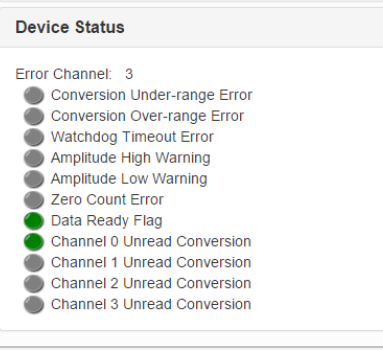
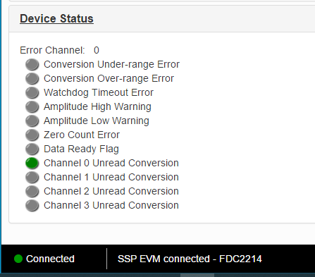
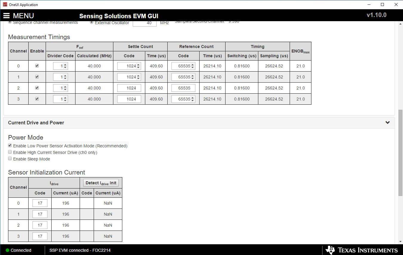
When I use FDC2214 EVM, I use the same ways as I mentioned. I directly went to the configuration page to see whether it could work normally. But I found two errors as shown in the first picture. To solve these 2 errors. I tried RESET_DEV =1 (in 15th ) in the register page and then did the configuration in the configuration page. I followed ‘EVM User’s Guide’. After I finished these setting. One of the error disappears, while another still exist (please see the second picture). And also I found that I could not ‘detect Idrive’ (please see the third picture). I am not sure which step I misunderstood. Could you please help me with that? Thank you very much.


  • Hello, 

    Yes you can configure the device through either the register page or the configuration page. The Data Ready Flag and Channel x Unread Conversions bits in the Status register will go high every time a measurement is taken. If you change the register update rate on the configuration page, you will see these flags toggle in the Device Status section of the configuration page. 

    The detect IDRIVE feature is no longer supported for this EVM so it will never return results. To set the IDRIVE setting, we recommend using an oscilloscope to view the sensor oscillation amplitude and make sure it is between 1.2V and 1.8V. It is best to set the amplitude closer to 1.8V without a target interaction as the amplitude will decrease with a target interaction. It is okay for the amplitude to drop below 1.2V with target interaction but going below 0.5V can cause the oscillation to fail. If you are using the sensors on the EVM, I would recommend using a value of 16 for the IDRIVE code. 

    Best Regards, 

    Justin Beigel

  • Many thanks for Justin's suggestions.
    When I changed the updated rate to 100ms, I did see the flags toggle in the Device Status section. I saw data from CIN1-4. So, the toggled flags do not mean that the EVM has any problem. It is a normal condition. Am I right about this point?

    Also, I saw your suggestions about IDRIVE. If I do not detect IDRIVE, I think the measured values are still reliable (like this EVM board). Am I right about this point?

    Actually, it's slightly hard to determine the oscillation amplitude for my case. I want to use this EVM for capacitance measurement. And I plan to replace the existing sensors part with two electrodes. Through the permittivity change between them to distinguish the permittivity. So, if just two simple electrodes, would you mind giving me some hints on how should I get the sensor oscillation amplitude?

    The last thing is that the part in my experiment moved all the time. Although I used coaxial ables, there is still some parasitic capacitance existing. I also bought FDC1004 EVM equipped with the active shield technique. And I found that 2214 does not has such a technique. For a moving object (contains attached electrodes), the FDC1004 EVM is a better choice than FDC2214 EVM. Is that right?

    I would appreciate it so much if you could bring me more information.
    Many thanks, and sorry to bother you.

    Best regards,
    Peggy

  • Hi Peggy,

    Our LDC experts are out today but should be back on Monday.  I will send this question to them when they return.

    Regards,

    Mekre

  • Hello, 

    Here are some answers to your questions: 

    So, the toggled flags do not mean that the EVM has any problem. It is a normal condition. Am I right about this point?

    Correct. The 'Data ready' and 'Channel x unread conversion' flags are normal during operation.  

    Also, I saw your suggestions about IDRIVE. If I do not detect IDRIVE, I think the measured values are still reliable (like this EVM board). Am I right about this point?

    The measurements are still valid, but the impacts of being outside the recommended range I mentioned will still apply. 

    would you mind giving me some hints on how should I get the sensor oscillation amplitude?

    Once you have your electrodes connected, I would try to set the IDRIVE based on the sensor amplitude for what you consider the normal or standard in your application. Setting the IDRIVE to be in the middle may be your best bet to stay within the voltage range if you don't know how your permittivity will change. Additionally, if you are seeing too much voltage change, you can add a parallel resistor to your LC tank to reduce the amount of Rp (and amplitude) change in your sensor. 

    For a moving object (contains attached electrodes), the FDC1004 EVM is a better choice than FDC2214 EVM. Is that right?

    The FDC1004 does do better at removing environmental impacts due to the included shield but we typically see this more used for liquid level detection. We have an out of phase implementation outlined in the Capacitive Sensing: Out-of-Phase Liquid Level Technique app note that discusses the benefits of different sensor designs. 

    Best Regards, 

    Justin Beigel

  • Hello Justin, Thanks so much for the detailed explanation.

    I am clear about the points you mentioned.
    The last issue is related to the FDC 1004 EVM.
    I also bought the FDC 1004 EVM. I found that even without connecting any DUT. There are still capacitance values. When I open data streaming, the value still shows a slight variation trend. I want to know how should I explain such fluctuation trends even without connecting any sensor? Thanks so much for your help.

    Best regards,
    Peggy

  • Hello,

    With no sensor connected, the parasitic capacitance of the board will still have an impact on the sensor measurement. This measurement will be relatively small which will mean that noise in the measurement will have a larger impact on the  result. If the measurement is still noisy when a sensor is connected, then additional debugging may be necessary. 

    Best Regards, 

    Justin Beigel

  • Hello,

    Many thanks for your help.

    Yeah, when I connected the sensor. There is still some variation, the value is slightly larger than 1pF with 0.2 std (in 100samples/s). In such a condition, do you think I should add debugging process? Also, could you please let me know how to debug generally?

    Another thing is that, the GUI will freeze if I select one or two channels on the 'data streaming' page. Only I select 4 channels and then start data streaming, the GUI is ok. Would you mind letting me know whether this kind of situation is normal and if I have to collect all 4 channels' data every time? Thank you very much.

    Best regards,
    Peggy

  • Hello, 

    If this meets your resolution requirements, then you do not need to debug further. It seems like you are already using the max RCOUNT setting so debugging would involve making sure the environment is as low noise as possible. 

    The GUI should be able to deselect channels without freezing. When you only select one or two channels, are the other channels still active in the configuration page? If yes, what happens if you disable the other channels before moving to the data streaming tab? 

    Thank you, 
    Justin Beigel

  • Hello Justin Beigel,


    Many thanks for your help.
    Actually, I tried that way you mentioned last time. Attached please see the figures. In Fig.1 I select CIN1 on the configuration page. After that, I started and stopped data streaming (in Fig.2 &3). But no data point I obtained here. Also no excel file I will gain. Finally, I went back to the configuration page, and this page is also frozen. I found that CIN1 on the configuration page will not change all the time.

    After that, I selected 'continuous Multi-channel measurements' on the configuration page and conducted CIN1 measurement. I saw the 'capacitance' value changes with time. But I still got nothing on the data streaming page (The same as Fig.2 &3).

    Finally, for the sampling rate, if I use 100 samples/second and open 4 channels. That means I could get 25 data points per second for each channel. Could you please let me know am I right about this point? But in the excel file, I got. In one second, only two data points for each channel. Is the two data points form the averaged value during measurement?

    Would you mind providing more information about that? Many thanks for your help all the time.

    Best regards,
    Peggy

  • Hello, 

    if I use 100 samples/second and open 4 channels. That means I could get 25 data points per second for each channel. Could you please let me know am I right about this point?

    Yes, this is correct.

    As for the excel file, the data output from the streaming page is not the same as the sampling rate of the device. In the Graph Configuration (button near top right of GUI window), the rate of data that uploads to the graph can be changed: 

    If you select EVM Output Rate, your excel file should have data for each sample the EVM takes. If your New Data Sample rate in the configuration is slower than the EVM sample rate, any samples in between will be ignored by the graph. 

    Best Regards, 

    Justin Beigel

  • Hello,

    Good day!

    Many thanks for your patiently reply about the sampling rate. I got it with your help.
    May I know how to solve the issue of freezing on the data streaming page when I select channels which lower than 4? Many thanks again.

    Also, I saw the manual about the differential mode, I also tried it. For the input channel, CIN1 is assigned for CHA, and CIN2 is assigned for CHB. I wanna know the CIN1-CIN2. according to the manual, the setup is right. Also for the shield, I followed the manual (attached please find it). The issue lies in obtained values are negative. I saw the liquid level measurement in the manual is always positive. Would you mind helping me with this point?

    Many thanks for your help!

    Best regards,
    Peggy

  • Hello, 

    For the freezing issue, I was able to duplicate it on a new EVM. To fix this, try updating the EVM using the 'Firmware' tab of the GUI. Make sure to select the correct firmware file. For a default installation, it will be in the following path: C:\ti\Sensing Solutions EVM GUI-1.10.0\EVM Firmware\FDC1004\EVM_FDC1004.txt. Once the update is complete, restart the GUI and try the measurements again. 

    For the differential measurements, a negative value will correlate to CIN2 being a larger capacitance than CIN1. This is a valid output for the device but if you are expecting a positive output, you can measure each channel single ended to determine what the expected capacitance is on each. From there, you can debug why either CIN2 is higher than expected or why CIN1 is lower than expected. 

    Best Regards, 
    Justin Beigel

  • Hi Justin Beigel,

    Thank you so much for your help. Actually, could I add one more thing related to parallel plate measurement through FDC 1004 EVM? I wanna measure the capacitance between two parallel electrodes. For my understanding, I connect positive copper (the top electrode) to CIN1 (CHA), and for the ground plate (the bottom electrode), I plan to connect it to CIN2(CHB). In that way, when I change the material inside the parallel plates, I could get the capacitance values caused by the material change. Am I right about the connection?

    Many thanks for your help again.

    Best regards,
    Peggy

  • Hello, 

    By connecting the GND plate to CIN2, you are then measuring the capacitance of each plate with respect to GND and then doing a differential measurement of the two rather than measuring the capacitance directly between the two plates. You can instead connect the GND plate to the same GND as the device and measure the capacitance using CIN1 only. Depending on the range of capacitance measurements, you may need to use the CAPDAC or another channel to offset CIN1 so the measurement is within the +/- 15pF measurement of the FDC1004. 

    Alternatively, you could implement something similar to the Out of Phase technique we recommend for liquid level sensing where the GND plate is attached to the opposite shield channel: 

    This requires that the plates be identical and you use a floating channel as the CHB input of the measurement. 

    Best Regards, 

    Justin Beigel

  • Hello ,

    Thank you for your quick reply.

    I've conveyed it to my customer.

    Have a good day .

    James