Other Parts Discussed in Thread: TMP117, TMP116,
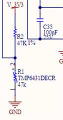
I have several boards each with a TMP6431DECR temperature sensor on them connected as shown.
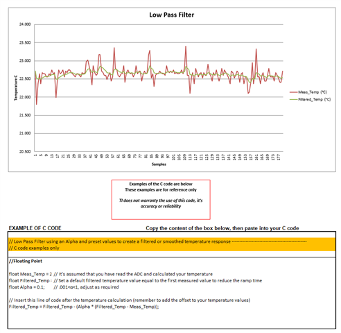
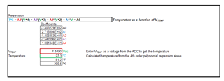
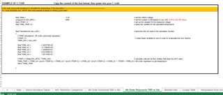
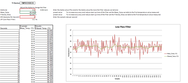
I'm using the voltage bias spreadsheet which I got from the "Thermistor design tool" link in the pdf for the data sheet which for me links here (as of today). In that spreadsheet there is a page titled "4th order polynomial tmp vs res" with coefficients to a formula for converting RTD resistance to temperature for this part. I'm using that formula to determine the temperature of the RTD by measuring the voltage on R1 to calculate the resistance and plugging that resistance value into that 4th order polynomial. Here is that formula:
| TºC = A4*(R^4) + A3*(R^3) + A2*(R^2) + A1*R + A0 | |||
| Coefficients | |||
| -2.739269E+02 | A0 | ||
| 1.150616E-02 | A1 | ||
| -1.621244E-07 | A2 | ||
| 1.389699E-12 | A3 | ||
| -4.856366E-18 | A4 | ||
Using that 4th order polynomial, the value of the temperature I calculate is always too high for all the boards I tried. They are all about the same amount too high as well, so I figure I must be doing something wrong in my calculation, but I can't figure it out.
Here's what I'm doing...
To make sure I know exactly what all the relevant values are, I pulled R2 off of one board and measured it to be 46,820 ohms then put it back in the circuit and measured these values with a DMM:
Voltage across R1 = 1.640V
Voltage across R2 = 1.653V
I also measured temperature on R1 with an external thermocouple to be 26.3C.
Those voltages and R1 value make R2=47,191 ohms. Plug that value into the polynomial above and calculate the temperature of R1 to be 29.9C which is 3.3C higher than what I measured with the thermocouple.