This thread has been locked.

If you have a related question, please click the "Ask a related question" button in the top right corner. The newly created question will be automatically linked to this question.

AFE3010: c2 is easily damaged during the test

Part Number: AFE3010

hi, 

      when there is a suddenly 2 peak leakage current  added , the voltage across C2 is as high as 210Vpeak. would you like kindly help give your any suggestions.

the detailed test report is attached for your reference.high voltge spike across C2 -AFE3010.pptx

  • Hey Ken,

    In general, the NGOUT pin voltage (with respect to GND pin) should only be 0V to 20V operational, and never exceed 26V (Absolute Maximum rating). So this capacitor (C2) only needs a voltage rating > 26V to be compliant with the AFE3010. When using the typical application schematic, there should be no reason that the voltage across C2 should reach the reported levels.

    The test schematic shown is confusing. Why are they emulating leakage current as shown? Are they using a two-core current transformer? The provided schematic shows that the core responsible for Neutral-ground detection has two coils wrapped around. One for the NGOUT pins (which is correct) and another that is connected some Zload between line side HOT and NEUTRAL. I do not see what this test could be accomplishing for measuring performance of AFE3010. To test AFE3010 performance for leakage (either rejection or detection), the Zload should be connected from HOT (load side) to NEUTRAL (line side) or Earth ground. Zload should be set so that leakage current starts from 3mArms (AFE3010 rejects) and increased beyond 4mA, where AFE3010 will trip in between 4mA and 6mA threshold zone, typical will be 5mA, when gain of amplifier network is properly tested and tuned to the specific transformer impedance.

    It is quite possible that the current (Iload) you are running through the 4-turn coil is generating a magnetic field within the core, which the 200-turn coil is then picking up and converting into a current source in-series with C2. This current will have to go somewhere (depending upon dynamic impedance of C2 because NGOUT is just a half-bridge switching circuit), thus voltage across C2 will begin to float.

    There really should be no other coil wrapped around this core. It is solely meant to transform the switching current of NGOUT into a common-mode current pulse on both HOT and NEUTRAL. Whenever there is a Neutral-to-ground fault, this common-mode current is split up and thus there is a differential current which is sensed by the second core with the 1000 turn coil that is being sensed by internal current-feedback amplifier responsible for sensing hot and neutral-to-ground faults.

    I recommend testing the device as I describe to see if the problem persists.

    Sincerely,

    Peter

  •  thanks for your explanations.

    do you mean that the test way in customer side is wrong for both Hot to Neural leakage and  Neutral -ground detection? any material about how to implement these leakage detection tests? and any instruction about current transformer design?

  • Hey Ken,

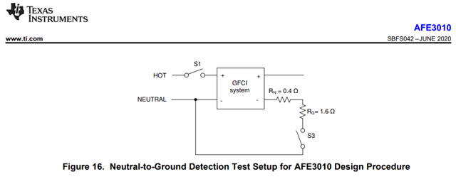
    Well I couldn't fully gather what the test setup was exactly. In order to evaluate the performance of this device, it must be setup as shown in the datasheet's typical application schematic (along with a dual core current transformer, one with a 1000-turn coil and another with a ~200 turn coil) or with the AFE3010EVM configured as instructed in the User's Guide. The purpose for the core with 1000-turn coil is to sense hot-ground faults, while the purpose for the core with the 200-turn coil is to help AFE3010 detect Neutral-ground faults. 

    In the datasheet, there is included a simple Neutral-ground test setup where the fault is connecting the load-Neutral to the line-neutral; however, it is also valid to connect load-neutral to Earth ground. 

    As for the standard hot-ground faults, the variable fault/leakage current should be connecting load-Hot to Earth ground/line-neutral. 

    These are essentially the test circuits shown in the UL943 standards document, which the AFE3010 was tested against (along with all variations) to ensure compliance.

    Sincerely,

    Peter